“Material Strength” Numerical Problems
Try to solve the following “Material Strength” numerical problems to clear the concepts in solving the numerical problems.
First of all go to the theory portion of the respective topic and then try to solve the numerical problems by yourself. If facing problem in solving the numerical, click on the Go to solution button to see the ready made solution placed at the bottom of each numerical problem.
01. PROBLEM – P100101
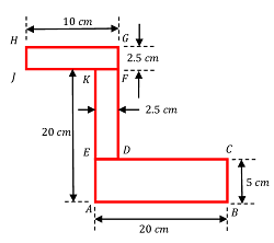
Find the centre of gravity of Z section as shown in figure below.
Keywords related to this problem.
02. PROBLEM – P100102
A square hole is punched out of a circular lamina, the diagonal of the square being the radius of the circle as shown in figure.
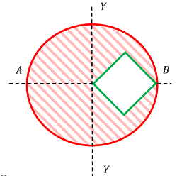
Find the centre of gravity of remainder section if ( r ) is the radius of circle.
Keywords related to this problem.
03. PROBLEM – P100103
A frustum of a solid right circular cone has an axial hole of ( 50 \ cm ) diameter as shown in figure.
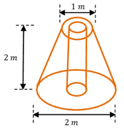
Determine the centre of gravity of the body.
Keywords related to this problem.
04. PROBLEM – P100104
Two halves of a round homogeneous cylinder are held together by a thread wrapped round the cylinder with two weights, each equal to ( P ) , attached to its ends as shown in figure. The complete cylinder weighs ( W \ kgf ) . The plane of contact of both of its halves is vertical.
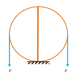
Determine the minimum value of ( P ) for which both halves of the cylinder will be in equilibrium on a horizontal plane.
Keywords related to this problem.
- Free body diagram.
- Conditions of static equilibrium.
- Centre of gravity.
- Centre of gravity of a solid cone.
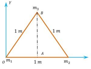
05. PROBLEM – P100105
Three masses of ( 3 ), \ ( 4 ) \ \& \ ( 5 ) \ kg are located at the corners of an equilateral triangle of side ( 1 \ m ) as shown in figure. Locate the centre of mass of the system.
Keywords related to this problem.
06. PROBLEM – P100106
A small sphere of radius ( R ) is held against the inner surface of a larger sphere of radius ( 6 R ) . The masses of larger sphere and smaller sphere are ( 4 M ) and ( M ) respectively. This arrangement is placed on a horizontal table. There is no friction between any surfaces of contact. The small sphere is now released. Find the co-ordinates of the centre of the larger sphere when the smaller sphere reaches the other extreme position?
Keywords related to this problem.
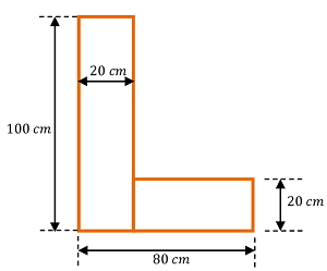
07. PROBLEM – P100107
Find moment of inertia about the centroidal XX and YY axis of the angle section as shown in figure.
Keywords related to this problem.
08. PROBLEM – P100108
A rectangular hole is made in a triangular section as shown in figure.
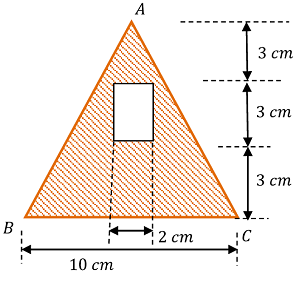
Determine moment of inertia of the section about XX axis passing through its centre of gravity and through the base BC .
Keywords related to this problem.
09. PROBLEM – P100109
Figure shows a built up section made of ( 12 \times 4 \ inch ) channels and ( 12 \ inch \times 3/4 \ inch ) plates. Find ( I_{xx} ) and I_{yy} through the centroidal axes, if I_{yy} for channel is ( 12.12 \ inch^4 ) .
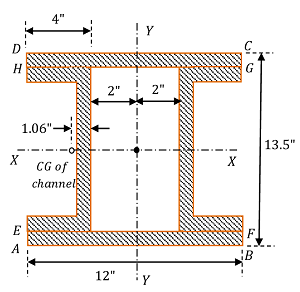
Area of channel section is ( 9.21 inch^2 ) . Position of centre of gravity from back of channel is ( 1.06 \ inch ) and I_{xx} for channel is ( 66.7 \ inch^4 ) .
Keywords related to this problem.
10. PROBLEM – P100110
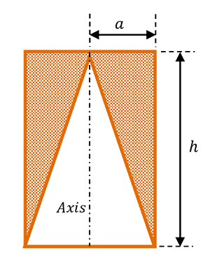
From a right circular cylinder a right cone of the same radius and altitude is cut out as shown in figure. If the radius is ( a ) and the altitude is ( h ) , find the moment of inertia of remaining solid about the axis of cylinder.
Keywords related to this problem.
11. PROBLEM – P100111
Four particles of masses of ( 4 \ kg ), \ ( 2 \ kg ), \ ( 3 \ kg ) \ \& \ ( 5 \ kg ) are located at the corners A, \ B, \ C \ \& \ D respectively of a square ABCD as shown in figure.
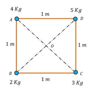
Calculate the moment of inertia of the system about (1) an axis passing through the point of intersection of the diagonals and perpendicular to the plane of the square (2) the side AB and (3) the diagonal BD .
Keywords related to this problem.
12. PROBLEM – P100112
A cantilever beam AB of length ( l ) is carrying a point load ( W ) at its free end B . Find and draw the shear force and bending moment diagram for the beam at important points.
Keywords related to this problem.
13. PROBLEM – P100113
A cantilever beam AB of length ( l ) is carrying a uniformly distributed load of ( w ) per unit length at its full length from A to B .
Find and draw the values of shear force and bending moment at important points and draw the diagram for the beam.
Keywords related to this numerical problems.
14. PROBLEM – P100114
An overhang beam AE of total length ( 15 \ m ) is carrying a uniformly distributed load of ( 1000 \ kg / m ) for ( 5 \ m ) from end A and ( 1600 \ kg / m ) for ( 2.5 \ m ) length from end E . The beam is carrying two point loads of ( 8000 \ kg ) and ( 4000 \ kg ) at points C \ \& \ D as shown in figure.
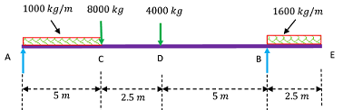
Draw the shear force and bending moment diagram for the beam. Also find the maximum bending moment acting any point of the beam.
Keywords related to this numerical problems.
15. PROBLEM – P100115
An simply supported beam AB of total length ( 5 \ m ) is carrying a uniformly distributed load of ( 1000 \ N / m ) for ( 2 \ m ) from end A and a clockwise couple of ( 1500 \ N \ m ) at ( 2.5 \ m ) from end B .
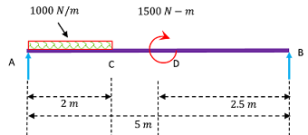
Draw the shear force and bending moment diagram for the beam. Also find the maximum bending moment acting any point of the beam.
Keywords related to this numerical problems.
16. PROBLEM – P100116
An ( I ) section beam is subjected to a bending moment of ( 500 \ kg \ m ) at its neutral axis. Section is shown in figure below.
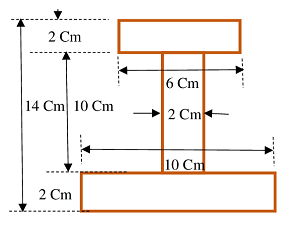
Find the maximum stress induced in beam.
Keywords related to this numerical problems.
17. PROBLEM – P100117
A timber beam of ( 100 \ mm ) wide and ( 200 \ mm ) depth is strengthen by a steel plate of ( 100 \ mm ) wide and ( 10 \ mm ) thick screwed at bottom surface of timber beam.
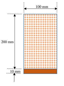
Find the moment of resistance of section if allowable stresses in timber and steel are ( 10 \ N / mm^2 ) and ( 150 \ N / mm^2 ) respectively. Take ( E_s = 20 E_t )
Keywords related to this problem.
18. PROBLEM – P100118
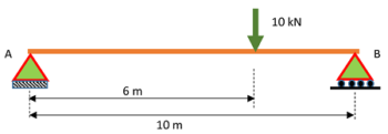
A simply supported beam ( AB ) of span ( 10 \ m ) is carrying a point load of ( 10 \ kN ) at a distance of ( 6 \ m ) from left end support A . Find out maximum deflection and slope of beam if ( E = 200 \ GN / m^2 ) and ( I = 1000 \times 10^6 \ mm^4 )
Keywords related to this problem.
- Differential equation of flexure.
- Double integration method to find slope and deflection.
- Young’s modulus of elasticity.
- Flexural rigidity.
19. PROBLEM – P100119
A cantilever ( 100 \ mm ) wide and ( 200 \ mm ) deep projects ( 2 \ m ) from a wall. The cantilever carries a uniformly distributed load ( 2 \ kN / m ) over a length of ( 1 \ m ) from free end and a point load of ( 1 \ kN ) at free end as shown in figure.
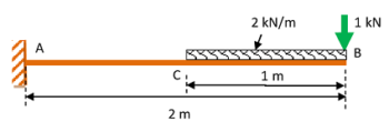
Find the slope and deflection at free end.
Keywords related to this problem.
- Differential equation of flexure.
- Double integration method to find slope and deflection.
- Young’s modulus of elasticity.
- Flexural rigidity.
20. PROBLEM – P100120
A simply supported beam AB of span ( 4 \ m ) is loaded with uniformly distributed load of ( 2 \ kN / m ) as shown in figure.
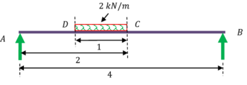
Determine deflection at C and slope at B by moment area method. Take ( EI = 12 \times 10^5 )
Keywords related to this problem.
21. PROBLEM – P100121
A beam ABCD is simply supported beam supported at its ends A and D over a span of ( 30 \ m ) . It is made up of 3 portions AB, \ BC \ \& \ CD each of ( 10 \ m ) in length. The moment of inertia of section over each of these individual portions is uniform and moment of inertia ( I ) values for them are ( I ), \ ( 3I ) \ \& \ ( 2I ) respectively, where ( I = 2 \times 10^6 cm^4 ) . Beam carries a point load of ( 15 ) tonnes at B and another load of ( 30 ) tonnes at C as shown in figure.
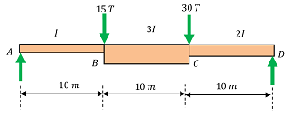
Neglecting self weight of beam, calculate the deflection at B and slope at C . Take the values of ( E ) , the modulus of material of beam ( E = 2 \times 10^6 kg/cm^2 ) uniform throughout the length.
Keywords related to this problem.
- Conjugate beam method to find slope and deflection.
- Mohr’s theorem – 1 for conjugate beam.
- Mohr’s theorem – 2 for conjugate beam.