What is called Relative Velocity?
The relative velocity is defined as the velocity of an object with respect to an observer on the same frame or another moving or stationary frame. It is the rate of change of relative positions of the two objects under consideration.
Therefore, Relative velocity of one object with respect to other object, is defined as the rate of change of position of the first object with respect to the second object.
Consider about two moving objects, object A and object B.
The rate of change of position of object A with respect to the position of object B is called relative velocity of object B with respect to object A. It is denoted by ( v_{BA} )
Assume that –
- ( v_A ) \text {and} ( v_B ) are the velocities of object A and object B respectively. We know that, rate of change of position of a moving object is the rate of change in displacement.
- Displacement of object A in time ( t ) is ( v_A t ) and displacement of object B in time ( t ) is ( v_B t )
Therefore, relative displacement of object B with respect to object A in time ( t ) will be –
\left ( v_B - v_A \right ) t
Rate of relative displacement will be –
\frac {\text {Relative displacement}}{\text {Time}} = \left [ \frac {\left ( v_B - v_A \right )t}{t} \right ] = \left ( v_B - v_A \right )
Therefore by definition, relative velocity of object B with respect to object A will be –
v_{BA} = \left ( v_B - v_A \right )
And relative velocity of object A with respect to object B will be –
v_{AB} = \left ( v_A - v_B \right )
Magnitude of Relative Velocity
Consider about two bodies A and B which are moving with velocities ( v_A ) \ \text {and} \ ( v_B ) respectively in directions making an angle ( \theta ) with each.
Let, we have to find the relative velocity of body A with respect to body B . This is done as follows –
- Draw OQ in proportional magnitude of ( v_A ) and same direction.
- Draw OP' in proportional magnitude of ( v_A ) but opposite in direction. Then, OP' will represent ( - v_B )
- Now relative velocity is obtained by vector addition of ( v_A ) \ \text {and} \ ( - v_B )
- Parallelogram OQRP' is now completed.
- Relative velocity ( v_{AB} ) is given by the diagonal OR of the parallelogram.
Consider about the space diagram for velocities in figure (A) and method to find their relative velocity in figure (B).

From vector diagram, relative velocity of body A with respect to body B –
v_{AB} = \sqrt {v^2_A + v^2_B + 2.v_A.v_B. \cos (180 \degree - \theta )}
Or, \quad v_{AB} = \sqrt {v^2_A + v^2_B - 2.v_A.v_B. \cos \theta}
Direction of Relative Velocity
Suppose that, the relative velocity ( v_{AB} ) makes an angle ( \beta ) with the direction of ( v_{A} ) .
Then, \quad \tan \beta = \frac {v_B \sin \left ( 180 \degree - \theta \right )}{v_A + v_B \cos \left ( 180 \degree - \theta \right )}
Or, \quad \tan \beta = \left ( \frac {v_B \sin \theta }{v_A - v_B \cos \theta } \right )
Or, \quad \beta = \tan^{-1} \left ( \frac {v_B \sin \theta}{v_A - v_B \cos \theta} \right )
This gives the direction of relative velocity ( v_{AB} ) .
See numerical problems based on this article.
Apparent weight in a Lift
When a man of mass ( m ) is standing on a weighing machine placed in a moving lift its weight read by the weighing machine is different than actual weight ( mg ) . This is called apparent weight of man.
This apparent weight of man is different for different instances depending upon the directions of movement of lift.
Consider about a man of mass ( m ) is standing on a weighing machine on a lift. Weight of man acts vertically downwards through the centre of gravity ( G ) of the man. Weight of man acts downward on weighing machine which offers a reaction ( R ) upwards.
The weighing machine gives reading for the reaction ( R ) . The reaction ( R ) is the force experienced by the man. So ( R ) is the apparent weight of man.

Now consider about the following conditions of apparent weight felt by the man.
Apparent weight when Lift moving Upward
When the lift moves upward with an acceleration ( a ) , the net upward force on the man is –
( R - mg ) = ma
Therefore, apparent weight will be –
R = m ( g + a )
So when a lift accelerates upwards the apparent weight of man increases.
Lift moving Downwards
When the lift moves downward with an acceleration ( a ) , the net downward force on the man is –
( mg - R ) = m a
Therefore, apparent weight will be –
R = m ( g - a )
So when a lift accelerates downwards the apparent weight of man decreases.
Lift is in Rest
When the lift is at rest, the acceleration is ( a = 0 ) .
Net force on the man is –
( R - mg ) = ma
= m \times 0 = 0
Therefore, apparent weight will be –
R = mg
So when a lift is at rest the apparent weight of man is equal to actual weight of man.
Lift is moving with Uniform Velocity
When the lift is moving with uniform velocity either upward or downward the acceleration ( a = 0 ) .
Net force on the man is –
( R - mg ) = m \times 0 .
Therefore, apparent weight will be –
R = mg
So when a lift is moving with uniform speed either upward or downward the apparent weight of man is equal to actual weight of man.
Lift is falling freely
If the supporting cable of the lift breaks the lift falls freely under gravity. Then ( a = g ) .
The net downward force on the man is –
R = m ( g - g ) = 0 .
Therefore, apparent weight of the man becomes zero. This is called the weightlessness.
Hence, a person develops a feeling of weightlessness when he falls freely under action of gravity.
So when a lift is falling freely the apparent weight of a man is equal to zero.
Tension in a Rope
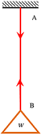
If a rope of negligible mass is loaded with a load ( W ) as shown in figure, then at every point of string, equal and opposite forces ( W ) will act. Each of these forces is called tension of rope. It is denoted by ( T ) .
Tension ( T ) at every point of rope is equal and opposite.
Consider a rope AB as shown in figure. End A is fixed to a nail and a load ( W ) is hanged at end B .
The rope is under pulling at A . Hence if equilibrium of point A is considered, tension ( T ) is shown by a downward arrow near A .
Again the rope is holding the weight ( W ) from falling down i.e. the rope is under pulling upward at point B . Hence, the arrow near point B is drawn upwards.
TO BE NOTED –
When a light string is passes round a smooth peg or pulley, its tension remains unchanged i.e. tension after pulley or peg is same as tension before pulley or peg.
See numerical problems based on this article.
Motion of connected bodies
Consider about two bodies of mass ( M ) \ \text {and} \ ( m ) connected by an in-extensible string passing over a smooth friction-less pulley as shown in figure.
Let, ( M > m ) . Then according to Newton’s second law of motion, the resultant downward force on mass ( M ) is –
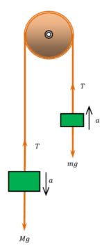
M a = ( M g - T ) ……. (1)
Resultant upward force on mass ( m ) is –
m a = ( T - m g ) ……. (2)
Adding equations (1) and (2), we get –
a ( M + m ) = ( M - m ) g
Or, \quad a = \left [ \frac {( M - m )}{( M + m )} \right ] g
Term \left [ \frac {( M - m )}{( M + m )} \right ] > 1 so \quad ( a < g ) \quad .
Hence, the acceleration ( a ) of two connected bodies is less than acceleration due to gravity.
Dividing equation (1) by (2), we get –
\left ( \frac {Ma}{ma} \right ) = \left ( \frac {M g - T}{T - m g} \right )
So, \quad \left ( \frac {M}{m} \right ) = \left ( \frac {M g - T}{T - m g} \right )
Or, \quad ( MT - M m g ) = ( M m g - m T )
Or, \quad ( M T + m T ) = 2 \ M m g
Therefore, \quad T = \left ( \frac {2 M m}{M + m} \right ) g
Free Body Diagram
A part diagram of a system showing all forces, moments, reactions at supports of a body is called a free body diagram.
Therefore, a free body diagram shows –
- Body outline dimensions.
- Magnitude and direction of all forces acting on body.
- All reactions on body or surface.
- Does not show supports.
Free body diagram is very useful in solving analytical problems related to complex force system. For illustration, free body diagram to solve a numerical problem related to friction force on inclined plane is shown below.
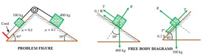
See numerical problems based on this article.