What is Kirchoff’s Law for electrical circuit?
Kirchoff’s law is very helpful in solving complicated electrical circuits consisting of a combination of cells and resistors. The law is consisting of two statements –
- Current law or junction law.
- Voltage law or loop law or mesh law.
Kirchoff’s Current Law
- Kirchoff’s current law is stated in two different ways. That –
- The sum of all currents entering at any point or junction must be equal to the sum of all currents leaving that point or junction.
- The algebraic sum of all currents meeting at a point or junction in a closed circuit is zero.
- It is also called as junction law.
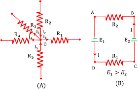
Consider about a point or junction O of an electrical network as shown in figure (A).
Let, ( I_2 ), \ ( I_5 ) are the currents entering to the point O and ( I_1 ), \ ( I_3 ), \ ( I_4 ) are the currents leaving the point O .
- Then, by Kirchoff’s first law \quad \sum I = 0
Or, \quad (I_1) + (- I_2) + (I_3) + (I_4) + (- I_5 ) = 0
Therefore, \quad ( I_2 + I_5 ) = ( I_1 + I_3 + I_4 ) ……… (1)
- The current entering to a junction point are taken as positive and currents leaving the junction point are taken as negative.
Kirchoff’s Voltage Law
- Kirchoff’s voltage law states that –
The sum of all the voltages i.e. potential differences across all elements and emf of all source of supply in any closed path or loop in a circuit is zero.
- It is also called as loop law or mesh law.
Consider a closed path or loop of an electrical network as shown in figure (B).
Let ( R_1 ), \ ( R_2 ) are two resistors and ( E_1 ), \ ( E_2 ) are the cells present in this loop.
- Then by Kirchoff’s second law we have –
\sum E + \sum V = 0
Sign convention of Kirchoff’s law
- In a circuit, electric current flows such that it emerges from positive terminal of a cell then travels through the loop of circuit and then re-enters to cell through the negative terminal of cell. Thus direction of flow of current inside a cell is from negative terminal to positive terminal.
- When we travel along the direction of flow of current the potential drop across a resistor is taken as positive.
- When we move along the direction of flow of current in loop and if the direction is from negative terminal to positive terminal of any cell then EMF of that cell is taken as positive.
Therefore, following sign conventions and applying Kirchoff’s second law in circuit in figure (B), we get –
( E_1 - R_1 - E_2 - R_2 ) = 0
Or, \quad ( E_1 - E_2 ) = ( R_1 + R_2 )
See numerical problems based on this article.
Wheatstone Bridge
Wheatstone bridge is an arrangement (circuit) of four resistors connected in the form of a bridge which is used for measuring an unknown resistor in terms of other three known resistors.
Consider about four resistors ( P ), \ ( Q ), \ ( R ), \ ( S ) connected in a bridge arrangement as shown in figure.
A source of emf is connected in between points A and C . A galvanometer is connected between the points B and D . ( P ) and ( Q ) are resistors of known resistances. Resistor ( R ) is adjustable. Unknown resistor is put in the arm ( S ) .
When key ( K ) is closed, galvanometer shows some deflection. Now the resistance ( R ) is adjusted such that deflection in galvanometer becomes zero. This situation is called balanced bridge.
- In a balanced bridge –
\left ( \frac { P }{ Q } \right ) = \left ( \frac { R }{ S } \right )
Therefore, \quad S = R \left ( \frac { Q }{ P } \right )
PROOF
Distribution of currents in the circuit is shown in figure. Applying Kirchoff’s law in the loop ABDA , we get –
- I_2 P - I_g G + I_1 R = 0 ………. (1)
Where ( G ) is the resistance of the galvanometer.
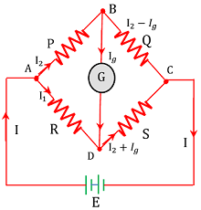
Applying Kirchoff’s law in the loop BCDB , we get –
- (I_2 - I_g) Q + (I_1 + I_g) S + I_g G = 0 ……… (2)
In balanced state, current through the galvanometer is zero i.e. ( I_g = 0 )
Hence, equation (1) becomes –
- I_2 P + I_1 R = 0
Or, \quad \left ( \frac { I_1 }{ I_2 } \right ) = \left ( \frac { P }{ R } \right ) ……… (3)
Similarly, equation (2) becomes –
- I_2 Q + I_1 S = 0
Or, \quad \left ( \frac { I_1 }{ I_2 } \right ) = \left ( \frac { Q }{ S } \right ) ……… (4)
From equation (3) and (4) we get –
- I_2 P + I_1 R = 0
Or, \quad \left ( \frac { P }{ Q } \right ) = \left ( \frac { R }{ S } \right )
The working method of Wheatstone bridge is called Null method. This method is independent of the internal resistance of source of EMF and resistance of the galvanometer.
Use of Wheatstone bridge circuit
Working principle of Wheatstone bridge is extensively used for working of many electrical measuring devices such as –
- Metre bridge – to measure an unknown resistance.
- Strain gauge – to measure heavy weights and strain in materials.
- LDR – Light dependent resistors are used in measuring of behavior of light.
- Thermometers – measurement of high temperature using thermocouples.
Metre Bridge
A meter bridge is an electrical apparatus used to measure the unknown resistance of a conductor. It consists of a wire of length one meter on which a jockey slides. Hence, it is called a meter bridge or a sliding wire bridge.
- The practical application of working principle of Wheatstone bridge is found in metre bridge.
Construction of Metre bridge
It consists of a Manganin or Constantan wire AB of length 1 \ m . This wire is of a uniform area of cross-section and is fixed on a wooden board parallel to a graduated metre scale. Two thick copper strips ( CS ) bent at right angles are fixed at the two ends of the wire. There is another thick copper strip fitted on the board in order to provide two gaps between the right angled strips. A resistance box ( R ) is fixed in one gap and the unknown resistance ( S ) is fixed in the other gap.
Terminal T of the central copper strip is connected with a jockey J through a sensitive galvanometer G . The jockey can be moved over the wire AB . A battery ( E ) through a key ( K ) is connected across the two ends of the wire.

Working principle of Metre Bridge
Key ( K ) is closes and resistance ( R ) is adjusted from known values of resistance from the resistance box. Now jockey J is moved over the wire AB such that the deflection in the galvanometer becomes zero.
Let, the resistance of the wire between A and J is ( P ) and the resistance of wire between B and J be ( Q ) .
If ( r ) is the resistance per unit length of wire then –
P = rl and Q = r ( 100 - l )
According to the principle of balanced Wheatstone bridge –
\left ( \frac { P }{ Q } \right ) = \left ( \frac { R }{ S } \right )
So, \quad S = R \left ( \frac { Q }{ P } \right )
Therefore, \quad S = R \left [ \frac { r ( 100 - l ) }{ r l } \right ]
= R \left [ \frac { ( 100 - l ) }{ l } \right ]
Thus by knowing the value of ( l ) and ( R ) , the value of unknown resistance can be calculated.
See numerical problems based on this article.