What is a Potentiometer?
A potentiometer is a device which is used to measure the EMF of a cell without drawing any current from it. Hence, a potentiometer gives very accurate results because the effect of internal resistance is nil as no current is drawn from the cell.
Advantages of Potentiometer
- A potentiometer works on null method. At null point, galvanometer shows zero deflection and current is not drawn from the cells under testing. So the measured or compared values of EMF of the cells are independent of their internal resistances.
- In balanced state ( null point ) the terminal potential difference is equal to the EMF of the cell and potentiometer acts like an ideal voltmeter of an infinite resistance.
- A potentiometer can be used for different purposes. (a) comparison or measurement of EMF of cells (b) measuring internal resistance of cells (c) measurement of resistance etc.
Applications of Potentiometer
A potentiometer is extensively used for following purposes –
- Comparing of electromotive force of two cells.
- To find internal resistance of a cell.
- Measuring of unknown resistance of a resistor.
Construction of Potentiometer
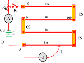
The schematic diagram of a potentiometer is shown in figure. It consists of a long uniform Manganin or Constantan wire AB fixed on a wooden board.
The long wire AB is consist of four equal parts each 1 metre long. These four parts of the wire are connected to one another by thick copper strips ( CS ) so that the combination acts as a single wire of length 4 \ m .
A steady current is allowed to flow through the wire AB . A sensitive galvanometer ( G ) is connected through a jockey ( J ) which is in contact and moved on wire AB . A metre scale is provided on the wooden board parallel to the length of the wire.
Working principle of Potentiometer
Working of a potentiometer is based on Ohm’s law i.e. resistance across any portion of a uniform wire is directly proportional to the length of that portion when a constant current flows through the wire.
Let, ( V ) is the potential difference across a portion of wire of length ( l ) , resistance ( R ) and uniform area of cross-section area ( A ) . If ( I ) is the current flowing through the wire then according to Ohm’s law –
V = IR = I \times \rho \left ( \frac { l }{ A } \right ) = \left ( \frac { I \ \rho }{ A } \right ) l = K l
Since, \left ( \frac { I \ \rho }{ A } \right ) is constant for a potentiometer.
Therefore, \quad V \propto l
Precautions for using of Potentiometer
Following precautions should be followed before using a potentiometer.
Checking of connection
To check the connection of a potentiometer, following procedure is followed.
- Switch K is closed and the jockey is pressed at point A . Direction of deflection of the galvanometer is noted.
- Now the jockey is pressed at point B . Again the direction of the deflection of the galvanometer is noted.
The deflections of the pointer of galvanometer when the jockey is at A and when it is at B must be in opposite directions.
EMF of main battery
In potentiometer a battery or cell is used as main source of supply in driving circuit which drives current in the device. The EMF of this main battery or driver cell should be higher than the EMF of either of any cells under testing or measurement.
If the EMF of the driver cell becomes less the testing cell will push current in the circuit and null point or balance point will not be obtained.
Comparison of two EMF
The setup and circuit diagram of potentiometer used to compare EMF of two cells is shown in figure.

STEP – 1
Switch S1 is closed, switch S2 is open and the jockey J is moved on the wire AB to find the null point (galvanometer shows zero deflection).
Let, at ( AJ = l_1 ) the galvanometer gives zero deflection.
At this state potential difference between A and J is equal to the EMF ( E_1 ) of the cell.
Therefore, \quad E_1 = V_{AJ}
But, according to the principle of potentiometer –
V \propto l_1
Therefore, \quad E_1 = V_{AJ} = Kl_1 ……. (1)
Where ( K ) is the constant of potentiometer.
STEP – 2
Now the switch S1 is opened, switch S2 is closed and jockey J is moved on the wire AB to find the null point ( galvanometer shows zero deflection ).
Let, at ( AJ = l_2 ) galvanometer gives zero deflection. At this state, potential difference between A and J is equal to the EMF ( E_2 ) of the cell.
Therefore, \quad E_2 = V_{AJ}
Or, \quad E_2 = V_{AJ} = Kl_2 …….. (2)
Dividing equation (1) by (2) we get –
\left ( \frac {E_1}{E_2} \right ) = \left ( \frac {l_1}{l_2} \right )
Finding Internal Resistance of a cell
The setup and connections for measuring the internal resistance of a cell is shown in figure.

STEP – 1
Key K_1 is kept close and K_2 is kept open.
Null point J is obtained by moving the jockey. At this stage, the potential difference across A and J is equal to the e.m.f ( E ) of the cell.
Let, at null point ( AJ = l_1 ) .
Then, \quad E = V_{AJ} = K l_1 …… (1)
STEP – 2
Now, key K_2 is closed so that a known resistance ( R ) is connected in parallel to the cell.
Null point J' is obtained by moving the jockey. At this stage, the potential difference across A and J' is equal to the terminal potential difference ( V ) of the cell.
Let, at null point, ( AJ' = l_2 )
Then \quad E = V_{AJ'} = K l_2 ……… (2)
Dividing equation (1) by (2), we will get –
\left ( \frac {E}{V} \right ) = \left ( \frac {l_1}{l_2} \right ) …….. (3)
We know for a cell –
r = \left ( \frac {E}{V} - 1 \right ) R ……. (4)
= \left ( \frac {l_1}{l_2} - 1 \right ) R
= \left ( \frac {l_1 - l_2}{l_2} \right ) R ……. (5)
Measuring Resistance by Potentiometer
The arrangement for measuring an unknown small resistance S using a potentiometer is shown in figure.

Key K_1 is kept closed and jockey is moved to find the null position.
Let, at point J on the wire AB of the potentiometer, galvanometer G gives no deflection.
Let, at null point ( AJ = l_1 ) \quad and \quad ( JB = l_2 )
Using the principle of a balanced Wheatstone bridge, we get –
\left ( \frac {l_1}{S} \right ) = \left ( \frac {l_2}{R} \right )
Or, \quad S = \left ( \frac {l_1}{l_2} \right ) R
If ( R ) is known, the value of unknown resistance ( S ) can be calculated.