What is a Parallel plate Capacitor?
Parallel plate capacitor is defined as a combination of two conducting parallel surfaces separated by a non conducting medium such that it can store electric charge.
- When the plates of capacitor are connected to the two terminals of a battery, the surfaces get charged by charges of equal magnitude but opposite sign.
- When the battery is disconnected, the charges on the conducting surfaces remains the same.
- Hence, a parallel plate capacitor is used for storing the charge.
Capacitance of Parallel plate Capacitor
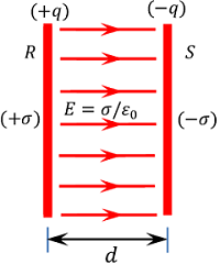
Consider about a parallel plate capacitor consisting of plates ( R ) \ \text {and} \ ( S ) separated by a distance ( d ) as shown in figure.
Let, ( + \sigma ) \ \text {and} \ ( - \sigma ) are the surface charge density of plates ( R ) \ \text {and} \ ( S ) respectively.
Then electric field between the plates will be –
E = \left ( \frac {\sigma}{\epsilon_0} \right ) ……… (1)
Here, ( \epsilon_0 ) is the absolute permittivity of free space or vacuum or air.
Let, ( V ) is the potential difference applied between the plates of capacitor.
Then, magnitude of electric field in terms of potential will be –
E = \left ( \frac {dV}{dr} \right ) = \left ( \frac {V}{d} \right )
So, \quad V = E d …….. (2)
Using equation (1) and (2), we will get –
V = \left ( \frac {\sigma }{\epsilon_0} \right ) d
= \left ( \frac {q}{\epsilon_0 A} \right ) d ………. (3)
Because \quad \sigma = \left ( \frac {q}{A} \right )
From definition of capacitance, we will get –
C = \left ( \frac {q}{V} \right )
= \left [ \frac {q}{\left ( \frac {q}{\epsilon_0 A} \right ) d} \right ]
= \left [ \frac {q \epsilon_0 A}{qd} \right ]
Therefore, \quad C = \left ( \frac {\epsilon_0 A}{d} \right )
Thus capacitance of a parallel plate capacitor is ( i ) directly proportional to the area of plates and ( ii ) inversely proportional to distance between plates.
TO BE NOTED –
Capacitance depends on – (1) The size i.e. area ( A ) of plates of capacitor and (2) Distance ( d ) between the plates. Thus, capacitance is determined by geometry of plates. It is a design parameter.
Capacitance doesn’t depends on – (1) The charge ( q ) on the plates. (2) Applied potential difference ( V ) between the plates.
Working principle of a Capacitor
Consider that a thin positively charged conducting plate A is kept in air. Let, another uncharged conducting plate B of similar size and shape is brought nearer to the plate A as shown in figure (A).
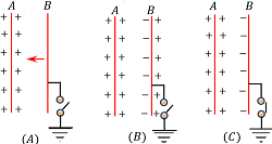
Then, negative charge will induce in nearer face of plate B and positive charge on farther face of plate B as shown in figure (B).
The induced negative charge on plate B will tend to decrease the potential of plate A ( because positive and negative charges will cancel to each other) where as induced positive charge will tend to increase the potential of plate B .
Since, induced negative charge on plate B is nearer to plate A in compared to the induced positive charge on plate B , therefore there will be a net decrease in the potential of plate A .
In order to keep the potential of plate A same as before, more charge can be supplied to it.
Thus the capacity of charged conducting plate A has increased by bringing an uncharged conducting plate B nearer to it.
If, farther side face of plate B is now connected to the earth, then all induced positive charges on plate B will drain to earth as shown in figure (C). Now, the plate B will have only induced negative charges.
This activity will further reduce the potential of plate A and thus more charges can be supplied to it for this. Thus a huge amount of charge can be stored in this arrangement.
In this way, a capacitor works to store huge amount of charge.
Effect of Dielectric on Capacitance
Capacitance of a parallel plate capacitor with free space between the plates is –
C_0 = \left ( \frac {\epsilon_0 A}{d} \right ) ……… (1)
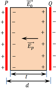
Due to charged plates of capacitor, an electric field ( \vec {E_0} ) will set up between the plates. Now, let a dielectric slab of thickness ( t ) is inserted between the plates as shown in figure.
Due to polarization of dielectric, equal and opposite induced charges will appear on the two surfaces of the slab. These induced charges give raise to induced electric field ( \vec {E_p} ) which is in a direction opposite to the direction of applied field ( \vec {E_0} ) .
Now, the reduced value of electric field in the dielectric is given by [ E = ( E_0 - E_p ) ] which exist in the region of thickness ( t ) and ( E_0 ) field exist in the region of thickness ( d - t ) .
Then, potential difference between the two plates of the capacitor will be –
V = E_0 \left ( d - t \right ) + E ( t )
= E_0 \left ( d - t \right ) + \left ( \frac {E_0}{K} \right ) ( t )
= E_0 \left [ \left ( d - t \right ) + \left ( \frac {t}{K} \right ) \right ] ……….. (2)
From definition of dielectric constant, we get –
K = \left ( \frac {E_0}{E} \right )
Also, \quad E_0 = \left ( \frac {\sigma}{\epsilon_0} \right ) = \left ( \frac {q}{A \epsilon_0} \right )
Then, equation (2) becomes –
V = \left ( \frac {q}{A \epsilon_0} \right ) \left [ \left ( d - t \right ) + \left ( \frac {t}{K} \right ) \right ] ……….. (3)
Therefore capacitance of the capacitor will be –
C = \left ( \frac {q}{V} \right ) = \left ( \frac {q A \epsilon_0}{q \left [ ( d - t ) + \left ( \frac {t}{K} \right ) \right ]} \right )
= \left ( \frac {\epsilon_0 A}{ \left ( d - t \right ) + \left ( \frac {t}{K} \right )} \right )
= \left ( \frac {\epsilon_0 A}{d \left [ \left ( 1 - \frac {t}{d} \right ) + \left ( \frac {t}{dK} \right ) \right ]} \right ) ………. (4)
Dividing equation (4) by equation (1), we get –
\left ( \frac {C}{C_0} \right ) = \left ( \frac {\epsilon_0 A}{d} \right ) \div \left ( \frac {\epsilon_0 A}{d \left [ \left ( 1 - \frac {t}{d} \right ) + \left ( \frac {t}{dK} \right ) \right ]} \right )
= \left [ \frac {1}{{\left [ \left ( 1 - \frac {t}{d} \right ) + \frac {t}{dK} \right ]}} \right ]
= \left [ \frac {1}{1 - \frac {t}{d} \left ( 1 - \frac {1}{K} \right ) } \right ]
So, \quad C = \left [ \frac {C_0}{1 - \frac {t}{d} \left ( 1 - \frac {1}{K} \right ) } \right ] ………. (5)
From equation (5), it is clear that ( C > C_0 )
Thus, capacitance of a capacitor increases by introducing a dielectric slab between the plates of a capacitor.
Effect of thickness of Dielectric slab
When ( t = d ) i.e. if thickness of dielectric slab is equal to the spacing between the plates then from equation (5), we have –
C = \left ( \frac {C_0}{\frac{1}{K}} \right ) = K C_0
Thus capacitance of a capacitor increases by a factor ( K ) .
When, \left ( t = \frac {d}{2} \right ) i.e. if thickness of dielectric slab is equal to the half of the spacing between the plates then from equation (5) we have –
C = \left ( \frac {2 K C_0}{K + 1} \right )
= \left ( \frac {2 K}{K + 1} \right ) C_0
When, \left ( t = \frac {2d}{3} \right ) i.e. if thickness of dielectric slab is equal to the spacing between the plates then from equation (5) we have –
C = \left ( \frac {3 K C_0}{K + 2} \right )
= \left ( \frac {3 K}{K + 2} \right ) C_0
Induced surface Charge density
Surface charge density developed in the dielectric medium between charged parallel plates is known as induced surface charge density.
Reduced value of electric field between two oppositely charged parallel plates is –
E = ( E_0 - E_p ) ……. (1)
But, \quad E_0 = \left ( \frac {\sigma}{\epsilon_0} \right )
And, \quad E_p = \left ( \frac {\sigma_p}{\epsilon_0} \right )
Also, \quad E = \left ( \frac {E_0}{K} \right ) = \left ( \frac {\sigma}{\epsilon_0 K} \right )
Therefore, equation (1) becomes –
\left ( \frac {\sigma}{\epsilon_0 K} \right ) = \left [ \frac {(\sigma - \sigma_p)}{\epsilon_0} \right ]
Or, \quad \sigma_p = \left ( \sigma - \frac {\sigma}{K} \right ) = \left ( \frac {K - 1}{K} \right ) \sigma
Since, \quad ( K > 1 ) so ( \sigma_p < \sigma )
Therefore, induced surface charge density in the dielectric is less than the surface charge density of plates.
SPECIAL CASE
If gap between the charged parallel plates is filled with a conducting material instead of a dielectric then –
( E = 0 )
Hence, equation (1) becomes –
( E_p = E_0 )
Therefore, \quad \left ( \frac {\sigma_p}{\epsilon_0} \right ) = \left ( \frac {\sigma}{\epsilon_0} \right )
Or, \quad \sigma_p = \sigma
Thus, induced surface charge density is equal to the surface charge density of plates.
See numerical problems based on this article.