What is an Electric Current?
Electric current is defined as the amount of electric charges flowing per unit time through any cross section of a conductor.
- In electrostatics, electric charge remains at rest. In electric current, this electric charge starts to flow through a material.
- This flow of electric charge through a conductor is called electric current.
- In flow of electric current, charges flow through a conducting material called conductor.
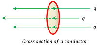
Consider about the cross sectional view of a conductor as shown in figure given.
Let, charge ( Q ) passes through a cross section of a conductor in time ( t ) .
- Then electric current through the conductor will be –
I = \left ( \frac { Q }{ t } \right )
Current Carrier
Current carrier are the agents which are responsible for flow of electric current through a material body.
- Every matter is made up of atoms and molecules.
- In a solid conductor, atoms are closely packed but valence electrons are not firmly attached to its nucleus.
- These valence electrons are free to move throughout the volume of the conductor. These are called free electrons.
- Hence, free electrons are current carrier in solids.
In other type of materials, following are current carriers –
- Ions are current carrier in solutions of ionic compounds.
- In molten metal, positive or negative ions are current carrier.
- Positively charged holes are current carriers in semiconductors.

080101 FLOW OF CHARGE THROUGH CONDUCTOR
Units of Electric Current
The SI unit of electric current is ampere.
One ampere electric current is defined as flowing of one coulomb of charge through any cross section of a conductor in one second.
Therefore, \quad 1 \ \text {Ampere ( A )} = \left ( \frac { 1 \ \text {Coulomb}}{ 1 \ \text {seconds}} \right ) = 1 \ \text {C-s}^{ - 1 }
= 10^3 \ \text {mili-ampere ( m-A )} = 10^6 \ \text {micro-ampere} ( \mu \ A )
Types of Electric Currents
Flow of electric currents are of different types. These are –
Steady Direct Current
An electric current is defined as steady direct current if its magnitude and direction doesn’t change with time.
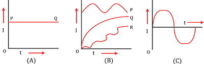
- Figure (A) shows a graph of variation of magnitude of steady current with time.
- As the magnitude and direction of steady direct current doesn’t change with time, it’s graph is a straight line parallel to time axis.
- In short form, it is called steady DC current.
Variable Direct Current
An electric current is defined as variable direct current if its magnitude changes with time but polarity or direction do not change.
- Figure (B) shows a graph of variable direct current whose magnitude changes with time.
- It may be of type P, Q or R as shown in figure.
Alternating Current
An electric current is said to be alternating current if its magnitude changes with time and polarity or direction also reverses periodically.
- Figure (C) shows a graph for magnitude of an alternating current.
- It is a sinusoidal curve.
- In short form, it is called an AC current.
Flow of electric current in a solid conductor
In solid conductors, free electrons move randomly with a thermal speed of about ( 10^5 - 10^6 ms^{ - 1 } ) at room temperature.
This is shown in figure (A).
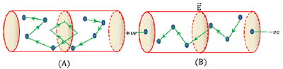
In absence of any external electric field, the flow of free electrons in the conductor is so oriented that the number of electrons crossing through a given cross section of conductor in any direction is equal to the number of electrons crossing through that cross section in opposite direction. Therefore, the net flow of electrons (or charge ) through the given cross section of the conductor becomes zero. Hence, electric current in the conductor is zero.
Now, let an electric field ( \vec { E } ) is applied across the ends of the conductor by connecting it with terminals of a cell as shown in figure (B). The direction of electric field in the conductor is from positive end to negative end.
The free electrons in conductor will experience an electrostatic force ( \vec { F } = - e \vec { E } ) in a direction opposite to the direction of electric field. This force produces acceleration in free electrons. Hence, there is a flow of free electrons in the direction opposite to the direction of applied electric field.
Thus, flow of free electrons occur from negative end towards positive end of the conductor. Therefore, electric current sets up in the conductor from positive end towards negative end of conductor.
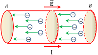
The whole process can be summarized with the help of given figure in following way –
In the conductor AB –
- End (A) is connected to positive terminal and end (B) is connected to negative terminal of cell.
- Thus, direction of electric field in the conductor will be from end (A) to end (B).
- So, flow of free electrons will occur in the direction from end (B) to end (A).
- Hence, flow of electric current occur in the direction from end (A) to end (B).
Drift Velocity
Drift velocity is defined as the average velocity of free electrons in a conductor in a direction opposite to the direction of the applied electric field.
Consider about a conductor under the influence of electric field ( \vec { E } ) .
- Electrostatic force experienced by free electrons will be –
\vec { F } = - e \vec { E }
Let, ( m ) is the mass of one electron.
- Then, acceleration produced in free electrons will be –
\vec { a } = \frac { \vec { F }}{ m }
Therefore, \quad \vec { a } = \frac { - e \vec { E }}{ m } ……. (1)
This acceleration exist for a very small duration and it dies when electron collides with vibrating ions of conductor.
This small interval of time between two successive collisions of free electrons and ions in the conductor, is called relaxation time or mean free time. It is denoted by ( \tau ) .
Therefore, \quad \tau = \frac {\text {Mean free path}}{\text {RMS velocity of electron}} = \left ( \frac { \lambda }{ v_{rms}} \right )
Hence, if ( \vec u ) is the initial velocity of an electron, then drift velocity will be –
\vec { v_d } = \vec { u } + \vec { a } \tau ……… (2)
But, in the absence of electric field, average velocity of electrons is zero.
Therefore, \quad \vec { v_d } = 0 + \vec { a } \tau = \left ( \frac { - e \vec { E }}{ m } \tau \right )
Hence, drift velocity of an electron is given by –
v_d = \left ( \frac { e E \tau }{ m } \right )
Mobility
Mobility of a current carrier is defined as the ratio of drift velocity to the applied electric field across the conductor.
Therefore, mobility of free electrons in a solid conductor is given by –
\mu = \left ( \frac { v_d }{ E } \right )
But, \quad v_d = \left ( \frac { e E \tau }{ m } \right )
Therefore, \quad \mu = \left ( \frac { e \tau }{ m } \right )
- SI unit of mobility is \quad \text {m-s}^{ - 1 } \ N^{ - 1 } \ C
Drift velocity and Electric current
Consider about a conductor of length ( l ) and cross sectional area ( A ) . Let ( V ) is the applied potential difference across the ends of the conductor.
From relation between electric field and potential, we get –
E = \left ( \frac { dV }{ dr } \right )
Therefore, magnitude of electric field set up in the conductor will be –
E = \left ( \frac { V }{ l } \right )
Let, ( n ) is the number of free electrons per unit volume of the conductor and ( e ) is the charge on each electron.
Then, total charge in the conductor will be –
Q = ( n A l ) e ……… (1)
If ( v_d ) is the drift velocity of free electrons, then time taken by the charge to cross the conductor length will be –
t = \left ( \frac { l }{ v_d } \right )
Now by definition of electric current –
I = \left ( \frac { Q }{ t } \right ) = \left ( \frac { n A l e }{ l / v_d } \right ) = \left ( n e A v_d \right )
Or, \quad I = \left ( n e A v_d \right ) ………. (2)
But \quad v_d = \left ( \frac { e E \tau }{ m } \right )
Therefore, \quad I = \left ( \frac { n e^2 A E \tau }{ m } \right ) ……… (3)
Since, ( n, \ e, \ A ) are constants.
So, \quad I \propto v_d
See numerical problems based on this article.