What is called “Moment of Resistance”?
When a beam is loaded with a load causing bending moment, it bends into the form of a circular arc. To resists bending and deformation, internal resistance sets up in the material cross section of of beam. Moment of this internal resistance about neutral axis of the section is called Moment of resistance.
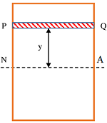
Consider about a transverse cross section of a rectangular beam as shown in figure. Let ( NA ) is the neutral axis of section.
Now, consider a small layer PQ of area ( \delta a ) at a distance ( y ) from neutral axis. Let, due to bending moment ( M ) , stress developed in this layer is ( f ) . Therefore, resistance developed in PQ will be –
\text {Resistance} = ( f \times \delta a )
= \left [ y \left ( \frac {E}{R} \right ) \times \delta a \right ]
Moment of this resistance about neutral axis ( NA ) is called Moment of resistance.
Therefore, magnitude of moment of resistance will be –
m = \left [ y \left ( \frac {E}{R} \right ) \times \delta a \right ] \times y
= \left ( \frac {E}{R} \right ) y^2 \delta a
Sum of all such moments about neutral axis ( NA ) must be equal to the applied bending moment ( M ) on beam.
Therefore, \quad M = \sum {m}
= \sum { \left ( \frac {E}{R} \right ) y^2 \delta a }
= \left ( \frac {E}{R} \right ) \sum {y^2 \delta a }
But, expression \left ( \sum {y^2 \delta a } \right ) represents moment of inertia of a section.
Hence, \quad \left ( \sum {y^2 \delta a } \right ) = I
Therefore, we can write the expression for bending moment as –
M = \left ( \frac {E}{R} \right ) \sum {y^2 \delta a }
= \left ( \frac {E}{R} \right ) \times I
So, \quad \left ( \frac {M}{I} \right ) = \left ( \frac {E}{R} \right )
This expression is called Equation of Bending Moment.
Thus, by combining the expressions for (1) Equation of bending stress and (2) Equation for bending moment we get –
\left ( \frac {f}{y} \right ) = \left ( \frac {M}{I} \right ) = \left ( \frac {E}{R} \right )
Section Modulus
Section modulus of a section is defined as the ratio of Moment of Inertia of the section about neutral axis and the distance of layer from neutral axis under maximum stress.
By equation of bending moment, moment of resistance is given by –
\left ( \frac {f}{y} \right ) = \left ( \frac {M}{I} \right )
So, \quad M = f \left ( \frac {I}{y} \right )
Let, ( f_c ) is the maximum compressive stress developed in outermost top layer which is at a distance ( y_c ) from ( NA ) and ( f_t ) is the maximum tensile stress developed in outermost bottom layer which is at a distance of ( y_t ) from ( NA ) .
Then, \quad M = f_c \left ( \frac {I}{y_c} \right ) = f_t \left ( \frac {I}{y_t} \right )
Here, \quad \left ( \frac {I}{y_c} \right ) = Z_c \ \text {and} \ \left ( \frac {I}{y_t} \right ) = Z_t are called modulus of section or section modulus.
Therefore, \quad M = ( f_c \times Z_c ) \quad or \quad M = ( f_t \times Z_t )
If a section is symmetrical, then ( y_c = y_t ) and maximum values of stress ( f_c ) and ( f_t ) will reach at the same time on extreme layers. Let it is represented by ( f_{max} ) .
Then, \quad f_{max} = f_c \ \text {or} \ f_t
And, for a symmetrical section \quad Z = Z_c \ \text {or} \ Z_t
Therefore, for a symmetrical section, moment of resistance will be \quad M = ( f_{max} Z )
Section Modulus of rectangular section
Consider about a beam of rectangular cross section of width ( b ) and depth ( d ) which is subjected to a bending moment ( M ) . Then, moment of inertia of rectangular section about neutral axis will be –
I = \left ( \frac {bd^3}{12} \right )
And distance of extreme layers is \quad y_c = y_t = \left ( \frac {d}{2} \right )
Therefore, \quad Z = \left ( \frac {I}{y} \right )
= \left ( \frac {bd^3}{12} \right ) \div \left ( \frac {d}{2} \right )
= \left ( \frac {1}{6} bd^3 \right )
Section Modulus of circular section
Consider about a beam of circular cross section of diameter ( d ) which is subjected to a bending moment ( M ) . Then moment of inertia of circular section about diameter will be –
I = \left ( \frac {\pi}{64} d^4 \right )
And distance of extreme layers y_c = y_t = \left ( \frac {d}{2} \right )
Therefore, \quad Z = \left ( \frac {I}{y} \right )
= \left ( \frac {\pi}{64}d^4 \right ) \div \left ( \frac {d}{2} \right )
= \left ( \frac {\pi}{32} \right ) d^3
Section Modulus of hollow circular section
Consider about a beam of hollow circular cross section of external diameter ( D ) and internal diameter ( d ) subjected to a bending moment ( M ) . Then, moment of inertia of a hollow circular section about diameter is given by –
I = \left ( \frac {\pi}{64} \right ) \left ( D^4 - d^4 \right )
And distance of extreme layers is \quad y_c = y_t = \left ( \frac {D}{2} \right )
Therefore, \quad Z = \left ( \frac {\pi}{64} \right ) \left ( D^4 - d^4 \right ) \div \left ( \frac {D}{2} \right )
= \left ( \frac {\pi}{32} \right ) \left ( \frac {D^4 - d^4 }{D} \right )
Distribution of Stress
From earlier discussions, we know the following facts –
- At neutral axis, there is no stress.
- All layers above neutral axis are subjected to compressive stress.
- And all layers below neutral axis are subjected to tensile stress.
- Stress at any particular layer is proportional to its distance from neutral axis.
Let, these stresses are expressed as ( f_c ) and ( f_t ) respectively. Therefore, \quad f \propto y .
Therefore, if we plot stresses ( f_c ) and ( f_t ) along the depth of section, then we will get a figure as shown. This is called Stress Distribution Diagram.
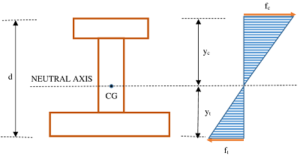
Position of neutral axis is shown in the figure. Maximum stress which may be either compressive stress or tensile stress occur at extreme outermost layers.
In a symmetrical section like square, rectangular or circular sections, centre of mass lies at geometrical centroid of section. Therefore, for symmetrical sections \quad f_c = f_t = f_{max} . And, \quad y_c = y_t = \left ( \frac {d}{2} \right ) . Here, ( d ) is the depth of the section.
Flitched beam
A flitched beam is made up by inserting a vertical steel plate layer between two wooden layers. All three layers are then held together with bolts and nuts.
A composite beam is made up of two materials. A higher strength material plate is bolted to strengthen a weak material section. Combined section is then behave as a single unit.
A timber beam or a cement concrete is strengthen by a steel plates or rods. This process of strengthening is called reinforcement.
EXAMPLE –
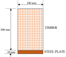
- Steel is very strong in tensile strength but it is very weak in compressive stress. Whereas timber is very strong in compression but weak in tension. Therefore, when a timber beam is used as a simply supported beam then steel plate is bolted at the bottom of timber section. A timber beam strengthen with steel plate at bottom is shown in figure.
- Reinforced cement concrete is another example of a composite beam. To increase the tensile strength, steel rods are inserted during casting in the region where tensile stress is more.
Composite section or flitched beam is used to save manufacturing cost cost and space.
Total moment of resistance of a composite section is equal to the sum of all moments of resistances of individual sections or layers.
So, if the moment of resistance of steel plate is ( M_s ) and that of timber is ( M_t ) , then total moment of resistance for the composite beam section will be –
M = M_s + M_t
See numerical problems based on this article.