What is Ampere’s Circuital Law?
Ampere’s Circuital Law is an approach to find the intensity of magnetic field at a point produced by a wire carrying a current. It states that –
The line integral of magnetic field around any closed path in free space is equal to absolute magnetic permeability \left ( \mu_0 \right) multiplied by the net current passing through any surface enclosed by that closed path.
- Ampere’s circuital law is not an universal law.
- It directly deals with only the steady currents.
- This law holds good for a closed path of any size and shape around a current carrying conductor.
- It is independent of the distance between conductor and closed path around the conductor.
According to Ampere’s Circuital Law, \quad \oint {\vec {B} \vec {dl}} = \mu_0 I
Where, ( \oint {\vec {B} \vec {dl}} ) represents the line integral of magnetic field around the closed path, ( \mu_0 ) is the permeability of free space and ( I ) is the net current enclosed by the closed path.
In general form if ( \theta ) is the angle between the current element vector ( \vec {dl} ) and magnetic field ( \vec {B} ) , then –
\oint B {dl} \cos \theta = \mu_0 I
- Importance of Ampere’s circuital law is similar to the Biot-savart law.
- This law helps to find the magnitude of magnetic field produced by a current carrying element.
Expression for Ampere’s circuital law
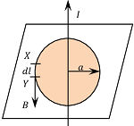
Consider about an infinite long straight conductor placed vertical as shown in figure. Let –
- The conductor is carrying a current ( I ) .
- Due to this current, the magnetic field lines are produced around the conductor in the form of concentric circles in horizontal plane.
- As per right hand thumb rule, the direction of magnetic field lines will be anti clockwise when vied from top of horizontal plane of figure.
From Biot-Savart law, magnetic field at a distance ( a ) from the conductor will be –
B = \left ( \frac {\mu_0}{4 \pi} \right ) \left ( \frac {2 I}{a} \right ) ………. (1)
Now, consider a imaginary circle of radius a around the wire. This circle is called an Amperian loop. Let –
- Length of a small element XY of the amperian loop is {dl} .
- So, in this case directions of ( \vec {dl} ) and ( \vec {B} ) are in same line, because direction of ( \vec {B} ) is along the tangent to the circular field lines around the conductor.
Thus, angle ( \theta ) between ( \vec {dl} ) and ( \vec {B} ) will be –
- – either ( 0 ) when current is flowing in upward direction in the conductor.
- – or ( \pi ) when current is flowing in upward direction in the conductor.
For the given figure, current is flowing in upward direction, so ( \theta = 0 ) \ \text {and} \ ( \cos \theta = 1 )
Therefore, product \quad \vec {B} \vec {dl} = B {dl} \cos \theta = B {dl}
Taking line integral for the entire closed path of Amperian loop, we get –
\oint {\vec {B} \vec {dl}} = \oint B {dl} ………. (2)
Substituting the value of ( B ) from equation (1), we get –
\oint B dl = \oint \left ( \frac {\mu_0}{4 \pi} \right ) \left ( \frac {2I}{a} \right ) {dl}
= \left ( \frac {\mu_0 2 I}{4 \pi a} \right ) \oint {dl}
But, \quad \oint {dl} = ( 2 \pi a ) ( Circumference of the Amperian loop )
Therefore, \quad \oint B dl = \left ( \frac {\mu_0 2 I}{4 \pi a} \right ) \left ( 2 \pi a \right )
= \mu_0 I
Thus, Ampere’s Circuital law is expressed as –
\oint {\vec {B} \vec {dl}} = \mu_0 I
Magnetic Field of infinite long wire
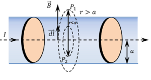
Consider about a conductor of infinite length and radius ( a ) carrying a steady current ( I ) . The current in the wire gives rise to a magnetic field around it. The magnetic field lines are represented by concentric circles with their centres on the axis of the wire.
The intensity of the magnetic field at a point will be different depending upon the distance of that point from the axis of wire. Let, find the magnetic field at following locations –
1.Field at a point outside the wire
Consider about a small length of the current carrying wire as shown in figure. Let, P_1 is a point outside the wire at a distance ( r ) from the axis of the wire as shown in figure. Here ( r > a ) .
Assume an Amperian loop passing through point P_1 . Now consider a small element of length ( dl ) of loop.
According to Ampere’s circuital law –
\oint {\vec {B}} d \vec {l} = \mu_0 I
Or, \quad \oint B {dl} \cos \theta = \mu_0 I
In this case the directions of ( \vec {dl} ) and ( \vec {B} ) are same.
Therefore, \quad \oint B {dl} \cos 0 \degree = \mu_0 I
Or, \quad B \oint {\vec {dl}} = \mu_0 I
So, \quad B \times 2 \pi r = \mu_0 I
Or, \quad B = \left ( \frac {\mu_0 I}{2 \pi r} \right ) ………… (1)
Therefore, magnetic field intensity at a point outside the wire varies inversely to the distance of the point from the axis of wire.
B \propto \left ( \frac {1}{r} \right )
2.Field on surface of wire
Magnetic field intensity on the surface of wire can be obtained by putting ( r = a ) in above equation. Therefore, intensity of magnetic field on the surface of wire will be –
B = \left ( \frac {\mu_0 I}{2 \pi a} \right ) ………… (2)
This is the maximum possible value of magnetic field intensity.
B_{Max} = \left ( \frac {\mu_0 I}{2 \pi a} \right )
3.Field at a point inside the wire
Consider about a point P_2 inside the wire at a distance ( r ) from the axis of the wire. In this case ( r < a ) . Assume that the current is uniformly distributed throughout the cross-section of the wire.
Then current through the circular area of wire of radius ( r ) will be –
I' = I \times \left ( \frac {\text {Cross sectional area of Amperian circle}}{\text {Cross sectional area of wire}} \right )
= I \times \left ( \frac {\pi r^2}{\pi a^2} \right ) = \left ( \frac {I r^2}{a^2} \right )
According to Ampere’s circuital law –
\oint {\vec {B}} \vec {dl} = \mu_0 I'
Or, \quad \oint B {dl} \cos 0 \degree = \mu_0 I'
So, \quad B \oint {\vec {dl}} = \mu_0 \left ( \frac {I r^2}{a^2} \right )
= \left ( \mu_0 \frac {I r^2}{a^2} \right )
Hence, \quad B \times 2 \pi r = \left ( \frac {\mu_0 I r^2}{a^2} \right )
Or, \quad B = \left ( \frac {\mu_0}{2 \pi} \right ) \left ( \frac {Ir}{a^2} \right )
Thus, \quad B \propto r
Variation of Magnetic Field
Following points should be noted for the variation of magnetic field produced by a current carrying wire. Let the radius of current wire is ( a ) and the point of consideration of magnetic field is at a distance ( r ) from the axis of wire.
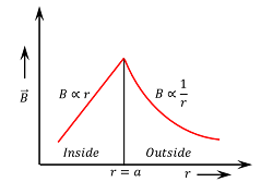
- When the point is inside the wire i.e. ( r < a ) the intensity of magnetic field ( B \propto r ) . Therefore, field intensity increases linearly with increase in distance from the axis of wire.
- When the point is on the surface of the wire i.e. ( r = a ) the intensity of magnetic field is maximum and is given by \left [ B_{Max} = \left ( \frac {\mu_0 I}{2 \pi a} \right ) \right ]
- When the point is outside the wire i.e. ( r > a ) the intensity of magnetic field \left [ B \propto \left ( \frac {1}{r} \right ) \right ] . Therefore, outside the wire body field intensity decreases with increase in distance from the axis of wire.
The variation of magnetic field ( B ) with distance ( r ) from the axis is shown in figure.