What is called an Inductor?
An inductor is component used in electrical or electronic circuits to store energy. The energy stored in inductor is in the form of magnetic energy.
- An inductor impedes or opposes any change in the current flowing through it. This property of an inductor is called its inductance.
- When an AC is applied to an inductor, then the circuit is called an inductive circuit.
- If a pure inductor or ideal inductor is used, it is called a Pure Inductive Circuit.
Inductance
When any change occurred in the electric current flowing through an inductor, it opposes the change in the current by inducing an EMF which drives a current in opposite direction. This property of an inductor is called its inductance.
Inductance of an inductor is defined as the ratio of the induced EMF to the rate of change in the current.
If, for rate of change in current \left ( \frac {dI}{dt} \right ) , the induced EMF in an inductor is ( \epsilon ) , then its inductance will be –
L = \left [ \frac {\epsilon}{\frac {dI}{dt}} \right ]
- Inductance is a result of the induced magnetic field on the coil.
AC current applied to an Inductor
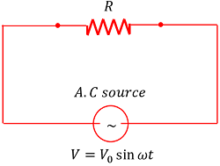
Consider about a pure inductive circuit as shown in figure. AC applied to a pure inductor of inductance ( L ) .
- The AC voltage applied to inductor is given by –
V = V_0 \sin ( \omega t ) ……… (1)
Phases of AC current in Inductor
- The induced EMF across the inductor will be –
\epsilon = - L \left ( \frac {dI}{dt} \right )

Minus sign indicates that induced emf opposes the growth of current in the circuit.
- In a pure inductive circuit, potential drop is zero. Therefore –
V + \left ( - \frac {dI}{dt} \right ) = 0
Or, \quad \left ( \frac {dI}{dt} \right ) = \left ( \frac {V}{L} \right )
From equation (1), we get –
\left ( \frac {dI}{dt} \right ) = \left ( \frac {V_0}{L} \right ) \sin ( \omega t )
Or, \quad dI = \left ( \frac {V_0}{L} \right ) \sin ( \omega t ) dt …….. (2)
Integrating both sides of the expression, we get –
\int dI = \left ( \frac {V_0}{L} \right ) \int \sin ( \omega t ) dt
So, \quad I = \left ( \frac {V_0}{L} \right ) \left [ - \frac {\cos ( \omega t )}{\omega} \right ]
= \left ( \frac {V_0}{L \omega} \right ) \left [ - \cos ( \omega t ) \right ]
Also from trigonometric relations, we get \left ( - \cos \omega t \right ) = \sin \left ( \omega t - \frac {\pi}{2} \right ) .
Therefore, \quad I = \left ( \frac {V_0}{L \omega} \right ) \sin \left ( \omega t - \frac {\pi}{2} \right )
Peak value of AC current in Inductor
Comparing above expression with the standard expression of alternating current [ I = I_0 \sin ( \omega t ) ] , we get the peak value of current as –
I_0 = \left ( \frac {V_0}{L \omega} \right )
Therefore, \quad I = I_0 \sin \left ( \omega t - \frac {\pi}{2} \right ) ………. (3)
Comparing equations (1) and (3), for AC applied to an inductor, we conclude that –
- Voltage and current have phase difference of \left ( \frac {\pi}{2} \right ) .
- Current lags behind the voltage by an angle \left ( \frac {\pi}{2} \right ) .
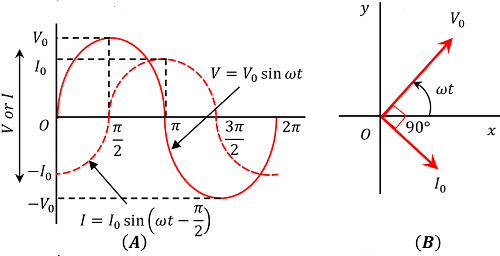
Figure (A) shows Time diagram and figure (B) shows Phasor diagram of a pure inductive circuit.
Inductive Reactance
Inductive reactance of a circuit is defined as the effective opposition offered by the inductor to the flow of current in the circuit.
Comparing the relation \left [ I_0 = \left ( \frac {V_0}{L\omega} \right ) \right ] and \left [ I_0 = \left ( \frac {V_0}{R} \right ) \right ] we conclude that ( L \omega ) has the dimension of a resistance.
- The term \left ( L \omega \right ) is called Inductive Reactance. It is represented by ( X_L )
Therefore, \quad X_L = L \omega
- In SI system the unit of inductive reactance is ohm.
TO BE NOTED –
(1) Behavior of a pure Inductor in DC supply –
- Inductive reactance of pure inductor is given by \left [ X_L = L \omega = 2 \pi L \nu \right ] .
So, it is a function of frequency ( \nu ) .
- For a DC source ( \nu = 0 ) .
Therefore, \left ( X_L = 0 \right ) . Thus a pure inductor offers no resistance to the flow of a DC.
- Hence DC can flow easily through an inductor coil.
(2) Behavior of pure Inductor at high frequency –
- Inductive reactance of pure inductor is given by \left [ X_L = L \omega = 2 \pi L \nu \right ] .
So it is function of frequency ( \nu ) .
- At very high frequency \left [ X_L \rightarrow \infty \right ]
Thus an inductor behaves as an open circuit at very high frequency.
AC applied to a Capacitor
When an alternating source is connected to an ideal capacitor, the circuit is called a pure capacitive circuit.
Consider about a pure capacitive circuit as shown in figure.

- The capacitor is periodically charged and discharged when an alternating voltage is applied to it.
The alternating voltage applied across the capacitor is given by –
V = V_0 \sin ( \omega t ) ……… (1)
Phase of AC current in Capacitor
Let, ( q ) is the charge on the capacitor at an instant.
- Then potential difference across the capacitor will be –
V_c = \left ( \frac {q}{C} \right )
But ( V_c ) is the applied voltage across the capacitor.
- Therefore, \quad V_c = V
Or, \quad V_c = V_0 \sin ( \omega t )
Also, \quad V_c = \left ( \frac {q}{C} \right )
- Therefore, \quad \left ( \frac {q}{C} \right ) = V_0 \sin ( \omega t )
Or, \quad q = V_0 C \sin ( \omega t )
Now, \quad I = \left ( \frac {dq}{dt} \right )
= \left ( \frac {d}{dt} \right ) \left [ V_0 C \sin ( \omega t ) \right ]
= V_0 C \left ( \frac {d}{dt} \right ) \left [ \sin ( \omega t ) \right ]
= V_0 C \omega \left [ \cos ( \omega t ) \right ]
= \left ( \frac {V_0}{1 / C \omega} \right ) \cos ( \omega t )
Also from trigonometric relations, we get –
\cos ( \omega t ) = \left [ \sin ( \omega t ) + \left ( \frac {\pi}{2} \right ) \right ]
Therefore, \quad I = \left ( \frac {V_0}{1 / C \omega} \right ) \sin \left ( \omega t + \frac {\pi}{2} \right ) ……… (2)
Peak value of AC current in Capacitor
Comparing this equation with standard equation of current \left [ I = I_0 \sin ( \omega t ) \right ] , we get the peak value of current as –
I_0 = \left [ \frac {V_0}{\left ( \frac {1}{C \omega} \right )} \right ]
Comparing equations (1) and (2), we conclude that –
- Voltage and current have phase difference of \left ( \frac {\pi}{2} \right ) .
- Current leads the voltage by an angle \left ( \frac {\pi}{2} \right ) .

Figure (A) shows Time diagram and figure (B) shows Phasor diagram of a pure Capacitive circuit.
Capacitive Reactance
The capacitive reactance of a circuit is defined as the effective opposition offered by a capacitor to the flow of electric current in the circuit.
Comparing the relations \left [ I_0 = \left ( \frac {V_0}{1 / C \omega } \right ) \right ] and \left [ I_0 = \left ( \frac {V_0}{R} \right ) \right ] , we conclude that \left ( \frac {1}{C \omega} \right ) has the dimension of a resistance.
- The term \left ( \frac {1}{C \omega} \right ) is called Capacitive Reactance. It is represented by ( X_C )
Therefore, \quad ( X_C ) = \left ( \frac {1}{C \omega } \right )
- In SI system unit of capacitive reactance is ohm.
TO BE NOTED –
Behavior of a capacitor in DC supply
- Capacitive reactance is given by the relation \left [ X_C = \left ( \frac {1}{C \omega} \right ) \right ] Or, \left [ X_C = \left ( \frac {1}{C \times 2 \pi \nu} \right ) \right ]
So, it is a function of frequency ( \nu ) .
- For a DC circuit, ( \nu = 0 )
Therefore, \left [ X_C = \left ( \frac {1}{0} \right ) = \infty \right ] . Thus a capacitor offers infinite opposition to the flow of DC current.
- So in DC circuit a capacitor behaves as an open circuit.
AC applied to a Resistor
When an AC source is connected to a resistor of pure resistance then this type of circuit is called a pure resistive circuit.
Consider about a pure resistive circuit as shown in figure.
Let, the applied alternating voltage in the circuit is –
V = V_0 \sin ( \omega t ) …….. (1)
Phase of AC current in resistor
Let, ( I ) is the current in the circuit at any instant ( t ) and ( I_0 ) is the peak value of the current.
- As per Ohm ‘s Law, across a resistor –
I = \left ( \frac {V}{R} \right )
Therefore, \quad I = \left ( \frac {V_0 \sin ( \omega t )}{R} \right )
= \left ( \frac {V_0}{R} \right ) \sin ( \omega t )
= I_0 \sin ( \omega t ) …….. (2)

Comparing equations (1) and (2) we see that phase difference between voltage and current is zero i.e. they are in the same phase.
If a graph for voltage and current in the resistor is plotted with respect to time ( t ) , it is observed that –
- Voltage and current are in same phase i.e. phase difference is zero.
- Both voltage and current have zero, maximum and minimum values at the same instants as shown in figure.
Time diagram for pure resistive circuit is shown in figure.
Power of a Resistor
Average values of alternating voltage and alternating current for full cycle are zero. But, power consumed or dissipated in a resistor is not zero.
- Instantaneous power dissipated in the resistor –
P = I^2 R = \left [ I_0 \sin ( \omega t ) \right ]^2 R
Or, \quad P = I_0^2 R \sin^2 ( \omega t )

- Therefore, Average power will be –
P = I_0^2 R \times Average of \sin^2 ( \omega t )
But, from trigonometric relation, we get –
\sin^2 \theta = \left [ \frac {1 - \cos ( 2 \theta )}{2} \right ]
Therefore, average of \left [ \sin^2 ( \omega t ) \right ] will be equal to the average of \left [ \frac {1 - \cos ( 2 \omega t ) }{2} \right ]
Now, average value of ( \cos 2 \omega t ) for full cycle can be obtained by integrating it within the limits \left ( t = 0 \right ) and \left ( t = T \right ) .
By integration, we get –
\left ( \frac {1}{T} \right ) \int\limits_{0}^{T} \cos ( 2 \omega t ) dt = 0
Therefore, average of \left [ \sin^2 ( \omega t ) \right ] is equal to \left ( \frac {1 - 0}{2} \right ) = \left ( \frac {1}{2} \right )
Hence, Average power is given by –
P = I_0^2 R \times Average of \sin^2 ( \omega t )
= \left ( \frac {1}{2} \right ) I_0^2 R
= \left ( \frac {I_0}{\sqrt {2}} \right )^2 R
= ( I_{rms} )^2 R