What is called Velocity Ratio?
Velocity ratio of a simple machine is defined as the ratio of distance moved by the effort and distance moved by the load.
Therefore, Velocity Ratio = ( Distance moved by Effort ) ÷ ( Distance moved by Load )
For a given machine, distance moved by load and distance moved by effort are not independent variables. These depend on the design parameters of a machine. Thus velocity ratio of a simple machine depends upon the machine parameters as discussed below.
Machine Parameters
A machine does a large work by using a small effort. Internal dimensions and configuration of a machine affects its working performance and efficiency. The dimensions and configurations which affect the performance of a machine are called machine parameters.
These parameters include –
- Fulcrum point.
- Load.
- Load point.
- Load arm.
- Effort.
- Effort point.
- Effort arm.
These machine parameters can clearly understood by considering about a straight lever as shown in figure.
Fulcrum point
A fixed point about which a lever is capable to rotate is called its fulcrum point.
- It is most important point for a lever.
- During working. fulcrum point of a lever remain fixed.
- In figure ( F ) is the fulcrum point of the lever.
Load
For a lever, load is defined as –
- A force, which is being overcome by a machine.
- A weight, which is being lifted by a machine.
- A work, which is being done by a machine.
Load point
The point of a lever at which external load is lifted or work is get as output, is called load point.
In figure point ( B ) is the load point of lever.
Load arm
Length of a straight lever is divided into two parts or lengths. Such as (1) Load arm and (2) Effort arm. One part of length is called load arm. It is attached with the out-put load or work out put.
In figure ( BF ) is the load arm.
Therefore, Load arm is the distance between load point ( B ) and fulcrum point ( F ).
Effort
An effort is defined as – (1) a force which is applied as input or (2) a work which is done to the machine as input work.
Effort point
The point at which input force or effort is applied to a lever, is called effort point.
In figure point ( A ) is the effort point.
Effort arm
Second part of the length of a lever which is attached with effort, is called effort arm.
In figure, ( AF ) is the effort arm. Effort arm is the distance between effort point ( A ) and fulcrum ( F ).

Velocity of load point & effort point
When a machine works, load point and effort point both move and changes its position with respect to time. Therefore, these points have certain velocity.
The distance traveled by the load point in a certain time is called velocity of load point.
Similarly, the distance traveled by effort point in the same time is called velocity of effort point.
Ratio of velocity of effort point and velocity of load point is known as Velocity ratio.
Therefore, V R = ( Velocity of Effort point ) ÷ ( Velocity of Load point )
Velocity Ratio of a Wedge
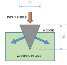
A wedge is consists of two inclined planes attached to form a sharp edge. It is used to take advantage of frictional force in a desired direction.
Consider about a wood cutter axes as shown in figure. When an effort is applied on the head of the axes, it penetrates deep in the wood.
Let, width of head of axes is ( W ) and its length is ( L ). Then, distance moved by effort is the length of wedge i.e. ( L ) and distance moved by load is the width of wedge i.e. ( W ).
Therefore, Velocity ratio of wedge will be –
V R = ( Length of wedge ) ÷ ( Width of wedge ) = L ÷ W
Hence, for the wedge shown in figure –
V R = ( L ) ÷ ( W ) = ( 30 ) ÷ ( 10 ) = 3
Velocity Ratio of an Inclined plane
A sloping or slanting surface or ramp is called an inclined plane.
For an inclined plane, distance moved by effort is the slant length of inclined plane and distance moved by load is the height or rise of inclined plane.
Consider an inclined plane as shown in figure.

Therefore, Velocity ratio of this inclined plane will be –
V R = ( Slant length of inclined plane ) ÷ ( Height or Rise of inclined plane )
Velocity Ratio of Lever
A lever is a rigid bar or a cylindrical rod capable to turn about a fixed point called fulcrum.
Consider a straight lever used for lifting a load as shown in figure.

When lever is operated let, in a certain time interval ( t ) the distance moved by effort point A is ( x ) and the distance moved by load point B is ( y ).
Then, velocity of effort will be [ (x) ÷ (t) ] and velocity of load will be [ (y) ÷ (t) ].
Therefore, velocity ratio of lever will be –
V R = ( x / t ) ÷ ( y / t ) = ( x ) ÷ ( y )
This is also called Speed ratio or Leverage ratio.
Velocity Ratio of Pulley
A pulley or sheave is a disc like object having a groove on its rim portion. In this groove a flexible rope or chain is wrapped to applying force or effort.
A simple pulley system is consists of one pulley.

In a simple pulley system –
\text {Distance moved by effort} = \text {Distance moved by load}
Therefore, for simple pulley system, \quad V R = 1
A two pulley system is consist of two pulleys.
In a two pulley system –
\text {Distance moved by effort} = 2 \times \ \text {Distance moved by load}
Therefore, for two pulley system, V R = 2
In this way, velocity ratio of a pulley system is expressed as –
Velocity ratio of a pulley system = Number of pulleys.
Now consider about a four pulley system as shown in figure.
Therefore, for a four pulley system, V R = 4
Velocity Ratio of Wheel & Axle

A wheel and axle device is made up of a circular frame called wheel disc which is mounted on a cylindrical shaft or rod called axle.
Consider about a wheel and axle system as shown in figure. Let, ( R ) is the radius of wheel disc and ( r ) is radius of axle.
In this system effort is applied on the rim of the wheel and load is lifted or work output is get at axle.
Therefore, Velocity ratio of a wheel and axle will be –
V R = ( R ) ÷ ( r )
Velocity Ratio of Screw

A screw is a circular cylindrical object which looks like a nail. Basically, it is an inclined plane wrapped around a circular cylinder.
Consider about a screw system as shown in figure.
Let, ( r ) is the radius of screw spindle and ( L ) is pitch or lead of screw thread.
When effort is applied at the screw head, then in one complete rotation of screw, distance moved by the effort is ( 2 π r ) and distance moved by the load is the advancement of screw in one rotation ( i.e. pitch or lead of screw ) which is ( L ).
Therefore, Velocity ratio of a screw will be –
V R = ( 2 π r ) ÷ ( L )