Find torque on current loop placed in a Magnetic Field.
When a current carrying loop or coil is placed in a magnetic field, it will experience a magnetic force which produces a torque in the current loop.
- The magnitude of the magnetic force developed on the current loop is according to the Lorentz Law.
- The direction of the magnetic force and so the torque developed on the current loop is according to the Fleming’s Left Hand Rule.
- Most of the electrical instruments like Galvanometer, Voltmeter, Ammeter etc. work on this principle.
- Therefore, measurement of torque acting on a current loop is most important for accuracy of electrical instruments.
Expression for Torque on Current loop
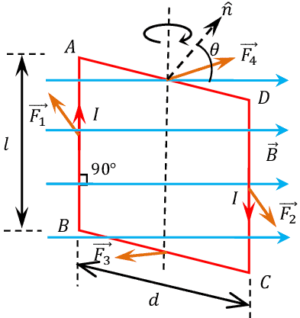
Consider about a rectangular loop ABCD of a conducting material placed in a magnetic field as shown in figure. Let –
- Length of the loop is ( l ) .
- Breadth of the loop is ( b ) .
- Loop is pivoted at the mid points of arms AD \ \text {and} \ BC .
- Intensity of uniform magnetic field ( \vec {B} ) .
- Current flowing in clockwise direction in the loop is ( I ) .
- The angle between the normal ( \hat {n} ) to the plane of the loop and the direction of magnetic field is ( \theta ) .
From Lorentz force, we know that net force acting on a conductor carrying current will be –
\vec {F} = I \left ( \vec {l} \times \vec {B} \right )
Force acting on arms AB & CD
Magnetic force acting on the arm AB of the loop will be –
\vec {F_1} = B I l ………. (1)
According to Fleming’s left hand rule, direction of force ( \vec F_1 ) is perpendicular to the length of the arm AB and directed penetrating inside the plane of paper.
Magnetic force ( F_2 ) acting on the arm CD of the loop will be –
\vec {F_2} = B I l ………. (2)
According to Fleming’s left hand rule, direction of force ( \vec {F_2} ) is perpendicular to the length of arm CD and is directed coming up from the plane of the paper. Therefore, direction of ( \vec F_2 ) is opposite to the direction of ( \vec F_1 ) .
Force acting on arms BC & AD
Magnetic force acting on the arm BC of the loop will be –
\vec {F_3} = B I b ………. (3)
According to Fleming’s left hand rule, direction of force ( \vec F_3 ) is perpendicular to the length of the arm BC and directed emerging up from the plane of paper. Magnetic force acting on the arm AD of the loop will be –
\vec {F_4} = B I b ………. (4)
According to Fleming’s left hand rule, direction of force ( \vec F_4 ) is perpendicular to the length of the arm AD and directed penetrating inside the plane of paper. Therefore, direction of ( \vec F_4 ) is opposite to the direction of ( \vec F_3 ) .
Torque on loop
Forces ( \vec {F_1} ), \ ( \vec {F_2} ), \ ( \vec {F_3} ), \ \text {and} \ ( \vec {F_4} ) , all are acting at the mid points of their respective arms.
- Forces ( \vec {F_3} ) and ( \vec {F_4} ) are equal, opposite in direction and parallel. But their line of action are passing through the pivot point. Hence, they will cancel to each other.
- Forces ( \vec {F_1} ) and ( \vec {F_2} ) are equal, opposite in direction and their line of action is different. Being opposite in direction, they will form a couple and try to rotate the loop in clockwise direction as shown in figure.
The magnitude of the torque ( \tau ) due to forces ( \vec {F_1} ) and ( \vec {F_2} ) will be –
\text {Torque} = \text {Force} \ \times \ \text {Moment arm}
Therefore, \quad \tau = F_1 \ \times \ DN
= B I l \ \times \ DN

= I \ \times \ \left ( \vec {l} \times \vec {B} \right ) \ \times \ DN
Vectors ( \vec {l} ) \ \text {and} \ ( \vec {B} ) are mutually perpendicular to each other and ( DN = b \sin \theta )
Therefore, \quad \tau = I ( l B \sin 90 \degree ) \ \times \ ( b \sin \theta )
= I ( l b ) B \sin \theta = I A B \sin \theta ………. (3)
Torque on a coil
Now consider that, the loop has ( N ) number of turns. Then net torque acting on the loop will be –
\tau_N = N I A B \sin \theta ……….. (4)
If the plane of loop makes an angle ( \alpha ) with the magnetic field ( \vec {B} ) . Then, \quad ( \theta + \alpha ) = 90 \degree
Hence, equation (3) becomes –
\tau_N = N I B \sin \left ( 90 \degree - \alpha \right ) = N I B \cos \theta
Radial Magnetic Field
Torque developed in a current loop or coil is given by the equation –
\tau_N = N I A B \sin \theta …….. (4)
If the value of ( \sin \theta ) attains the maximum value then maximum torque will develop in the loop. But maximum value of ( \sin \theta = 1 ) .
Therefore, when maximum torque is acting on the loop, then ( \theta = 90 \degree ) . Therefore, maximum value of torque will be –
\tau_{Max} = N I A B \sin 90 \degree = N I A B …….. (5)
Therefore, magnetic field which is parallel to the plane of the loop or coil is called radial magnetic field. This magnetic field develops maximum torque in the loop or coil.
Dipole Moment of current loop
Torque developed in a current loop is given by the equation –
\tau = I A B \sin \theta ………. (3)
The product ( I A ) in equation (3) is known as magnetic dipole moment of the current loop. It is denoted by ( m ) .
Therefore, \quad \text {Magnetic dipole moment of current loop} ( m ) = I A
If the loop has ( N ) number of turns,
Then, \quad m = N I A