What is an Electric Circuit?
An electric circuit is a closed loop or path consisting of a network of electrical conductors, resistors, electronic components and other electrical elements where electrons can flow through it uninterruptedly. An electrical circuit mainly contains –
- One or more sources of electrical power which can be a cell or or combination of cells called a battery or an AC supply source, which drives the flow of current through the circuit.
- One or more elements consuming electrical energy or power.
- Switching element for connecting (ON) and disconnecting (OFF) the power supply through the circuit.
- Safety elements for safeguard of the components in the circuit in case of accidental situations. These may be circuit breakers, relays, fuses etc.
- A series of conductors or wires which integrate and connects the above components together to form a closed loop.
Therefore, Electric circuit is defined as a continuous path which allows uninterrupted flow of electric current.
Types of Electric Circuit
Depending upon the continuity of flow of electrons, an electric circuit may be a closed circuit or an open circuit.
Open circuit
An open circuit is one where the continuity of flow of electric current has broken temporarily by an interruption.
The interruption in the flow of electric current in open circuit may be (1) intentional or (2) accidental.
(1) Intentional open circuit
Intentional open circuits are used for various maintenance purpose or service purposes. This is done by using ON-OFF switches, contactors, relays, fuses etc. in the circuit.
(2) Accidental open circuit
An accidental open circuit happens due to actuation of a safety devices or elements in a circuit which are install in the circuit for safe guard of electrical appliances. These are thermal relays, fuses, circuit breakers etc.
Accidental failures of circuit elements also causes an open circuit to occur.
Closed Circuit
A working circuit is a closed circuit. An accidental open circuit is attended for maintenance to bring it in close circuit. This is done by closing of all switches and replacement or resetting of failed elements in the circuit.
A closed circuit is one which provides uninterrupted and continuous flow of electric current through the circuit.
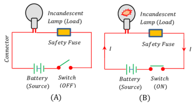
Opening and closing of a circuit by operating with switch element can be represented in a diagram as shown in figure below –
- Consider about the figure (A). Switch is in “OFF” position which breaks the flow of current from the source. It is an open circuit.
- In figure (B) closing of switch in “ON” position maintains a closed circuit.
Circuit Elements
An electric circuit mainly consists of following types of electrical devices called circuit elements.
(1) Electrical Load –
These are the elements which consumes most part of electric energy in a circuit. All electrical loads are classified into three main categories – Resistance or resistive load, Capacitance or capacitive load and Inductance or inductive load.
Examples of electric loads are – Bulbs, Fans, Motors, TV, Fridge, transformer etc.
(2) Power Source –
This provides the source of electric energy in a circuit.
Examples are emf of cell, battery, generators, AC mains etc.
(3) Connectors –
This element provides continuity of a circuit. These are wires, conductors, joiners etc.
(4) Switch –
These elements are used to provide discontinuity of the flow of electric current in the circuit as per our need. Switches, contactors are used for switching “ON” or “OFF” of the appliances. Fuses, circuit breakers, relays etc. are used for safety measure and to prevent electrical mishap.
Ohmic Circuit Element
The materials or circuit elements which strictly obey the Ohm’s law are known as Ohmic circuit elements.
In Ohmic elements ( V ) is directly proportional to ( I ) . The graph between ( V ) and ( I ) for Ohmic materials or elements is a straight line passing through the origin as shown in figure (A).
Examples of Ohmic circuit elements are (1) all metallic conductors (2) resistances called resistors etc.

Non-ohmic Circuit Element
The materials or circuit elements which not obey the Ohm’s law are known as non-ohmic circuit elements.
In non-ohmic elements ( V ) is not directly proportional to ( I ) . The graph between ( V ) and ( I ) for non-ohmic materials or elements is not a straight line. It is a curve as shown in figure (B).
Examples of non-ohmic circuit elements are (1) semi-conductors (2) vacuum tubes (3) transistors (4) thermistors (i.e. highly temperature dependent resistors) etc.
Combination of Resistors
The electrical elements which strictly obeys Ohm’s law are called resistors.
In an electric circuit various resistors are found connected one to another in various ways to form a complicated network.
If sorted out the resistors are found to be connected in two ways –
- Series combination of resistors.
- Parallel combination of resistors.
Series combination of Resistors
Two or more resistors are said to be connected in series if same current flows through all the resistors when a potential difference is applied across the combination.
Consider three resistors of resistances ( R_1 ), \ ( R_2 ) \ \& \ ( R_3 ) which are connected in series as shown in figure.
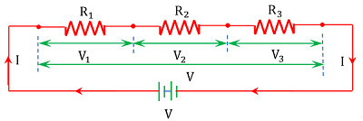
Since all the resistors are connected in series so same current will flow from each of them.
Let ( I ) is the current flowing through each of the resistors and ( V ) is the potential difference across the combination.
If ( V_1 ), \ ( V_2 ) \ \& \ ( V_3 ) are the drop of potential across the respective resistors.
Then, \quad V = ( V_1 + V_2 + V_3 )
But from ohm’s law for a resistor –
V = IR
Therefore, \quad V = ( IR_1 + IR_2 + IR_3 )
If ( R_s ) is the equivalent resistance of a single resistor of equivalent circuit, then –
V = IR_s
Or, \quad IR_s = ( IR_1 + IR_2 + IR_3 )
Therefore, \quad R_s = ( R_1 + R_2 + R_3 )
Therefore, equivalent resistance for a combination of resistors connected in series is equal to the sum of individual resistances.
Equivalent Resistance in series \quad R_s = ( R_1 + R_2 + R_3 )
See numerical problems based on this article.
Parallel combination of Resistors
Two or more resistors are said to be connected in parallel if same potential difference exist across all the resistors in the circuit.
Consider that three resistors of resistances ( R_1 ), \ ( R_2 ) \ \& \ ( R_3 ) are connected in parallel as shown in figure.
Let ( I ) is the current pushed by the source e.m.f cell. This current is divided into three components at the junction point (A).
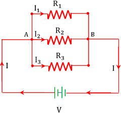
Thus, amount of current ( I ) flowing through each resistor will be different but potential difference ( V ) will be the same.
Therefore, \quad I = ( I_1 + I_2 + I_3 )
Also, \quad V = V_1 = V_2 = V_3
- Therefore, \quad V = I_1 R_1 = I_2 R_2 = I_3 R_3
If ( R_p ) is the equivalent resistance of a single resistor of equivalent circuit, then –
I = \left ( \frac { V }{ R_p } \right )
Also \quad I_1 = \left ( \frac { V }{ R_1 } \right ) \quad I_2 = \left ( \frac { V }{ R_2 } \right ) \quad \& \ I_3 = \left ( \frac { V }{ R_3 } \right )
- Therefore, \quad \left ( \frac { V }{ R_p } \right ) = \left [ \left ( \frac { V }{ R_1 } \right ) + \left ( \frac { V }{ R_2 } \right ) + \left ( \frac { V }{ R_3 } \right ) \right ]
Or, \quad \left ( \frac { 1 }{ R_p } \right ) = \left ( \frac { 1 }{ R_1 } + \frac { 1 }{ R_2 } + \frac { 1 }{ R_3 } \right )
- Therefore, \quad R_p = \left [ \frac { R_1 + R_2 + R_3 }{R_1 R_2 R_3} \right ]
Therefore, reciprocal of equivalent resistance for a combination of resistors connected in parallel is equal to the sum of reciprocals of individual resistances.
Equivalent Resistance in parallel \quad R_p = \left [ \frac { R_1 + R_2 + R_3 }{R_1 R_2 R_3} \right ]
See numerical problems based on this article.