What is a Transformer?
A transformer is an electrical device used to convert low alternating voltage at higher current into high alternating voltage at lower current.
Therefore, a transformer is used to increase or decrease alternating voltage. It works on the principle of electromagnetic induction.
Types of Transformer
Transformers are of two types –
- Step-up transformers.
- Step-down transformers.
Step-up Transformer
The transformer which converts low alternating voltage at higher current into a high alternating voltage at lower current is called step-up transformer.
In other words, a step-up transformer gives increased alternating voltage output.
Step-down Transformer
The transformer which converts high alternating voltage at lower current into low alternating voltage at higher current is called step-down transformer.
In other words, a step-down transformer gives decreased alternating voltage output.
Construction of a Transformer
A transformer is consists of two separate coils made of insulated wire wound on two opposite sides of an iron core as shown in figure. One of the coil is connected to an AC supply as input. This coil is called primary coil ( P ) .
The output alternating voltage ( E_s ) is taken across the secondary coil to which external load is connected. This coil is called secondary coil ( S ) .
The primary coil along with the source of alternating voltage ( E_p ) is called primary circuit. The secondary coil along with external load is called secondary circuit.
Construction of a typical transformer is shown in figure below.
Working principle of Transformer

Working of a transformer is based on the principle of mutual induction. When an alternating source of EMF ( E_p ) is connected to the primary coil, an alternating current flows through it.
Due to the flow of alternating current in the primary coil, an alternating magnetic field is produced which brings a change in magnetic flux linked with the secondary coil. This changing in magnetic flux induces an induced EMF ( E_s ) in the secondary coil.
Let, ( N_p ) and ( N_s ) are the number of turns in the primary and secondary coils respectively. According to Faraday’s law of induction, the induced EMF in the primary coil will be –
E_p = - N_p \left ( \frac {d \phi}{dt} \right ) ……. (1)
And the induced EMF in the secondary coil will be –
E_s = - N_s \left ( \frac {d \phi}{dt} \right ) …….. (2)
Dividing equation (2) by equation (1), we get –
\left ( \frac {E_s}{E_p} \right ) = \left ( \frac {N_s}{N_p} \right ) = K …… (3)
Here \left [ \left ( \frac {N_s}{N_p} \right ) = K \right ] is constant called Transformation Ratio or Turns Ratio of the transformer.
- For a step-up transformer ( K > 1 ) . In this case ( N_s > N_p ) and ( E_s > E_p ) .
- For a step-down transformer ( K < 1 ) . In this case ( N_s < N_p ) and ( E_s < E_p ) .
Energy loss in Transformer
Loss of electrical energy in a transformer takes place due to –
- Copper loss.
- Leakage loss.
- Iron loss.
- Vibration loss.
Copper loss
Energy lost in windings of a transformer is known as copper loss.
Primary and secondary coils of a transformer are generally made up of copper wires. These copper wires have resistance ( R ) . When current ( I ) flows through these wires, power loss amounting to \left ( I^2 R \right ) takes place. This loss appears as heat produced in primary and secondary coils.
Copper losses can be reduced by using thick wires for the windings.
Leakage loss
In actual transformer, the coupling between primary and secondary coil is not perfect. That means the magnetic flux linked with the primary coil is not equal to the magnetic flux linked with the secondary coil. There is some leakage of magnetic flux.
Therefore certain amount of electrical energy supplied to the primary coil is wasted as leakage loss.
Iron loss
Iron loss is of two types –
- Eddy Current loss -: When a changing magnetic flux links with the iron core of the transformer, eddy currents are set up. These eddy currents in the iron core produces heat which leads to the wastage of energy. This energy loss can be reduced by using laminated iron cores.
- Hysteresis Loss -: When alternating current passes through the primary coil, the iron core of the transformer is magnetized and demagnetized over a complete cycle. Some energy is lost in magnetizing and some energy lost in demagnetizing of iron core. The energy loss in a complete cycle is equal to the area of the hysteresis loop.
Vibration loss
A transformer produces humming noise due to magnetostriction effect. Some energy is lost in the form of mechanical energy to produce vibration in the core.
Efficiency of a Transformer
Efficiency of a transformer is defined as the ratio of output power to the input power.
Therefore, efficiency of a transformer is defined as –
\eta = \frac {\text {Output Power}}{\text {Input Power}}
Let, ( I_p ) and ( I_s ) are the currents in the primary and secondary coils respectively. Then –
- Output power is ( E_s I_s )
- Input power is ( E_p I_p )
Therefore, efficiency of transformer will be –
\eta = \left ( \frac {E_s I_s}{E_p I_p} \right )
For an ideal transformer, there is no energy loss.
Therefore, \quad \text {Output power} = \text {Input power}
Or, \quad E_s I_s = E_p I_p
Or, \quad \left ( \frac {E_s}{E_p} \right ) = \left ( \frac {I_p}{I_s} \right )
An ideal transformer has no loss of energy. Therefore, efficiency of an ideal transformer is ( 100 \% ) . Thus, for an ideal transformer, \quad \text {Gain in voltage ratio} = \text {Loss in current ratio}
A.C Generator
AC generator is an electrical machine used to convert mechanical energy into electrical energy. It receives mechanical energy as input and gives electric current as output.
An AC generator is also called an Alternator or AC dynamo. It works on the principle of electromagnetic induction i.e., when a coil is rotated in the region of a magnetic field, an induced EMF is produced in it.
The main components of an AC generator are shown in figure.
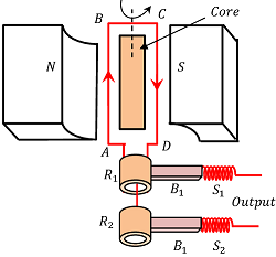
Armature
Armature is a coil consists of a large number of turns of insulated copper wire wound over a soft iron core.
Strong magnet
A strong permanent magnet or an electro-magnet is used to produce a strong magnetic field. Poles of the magnet are cylindrical and widened in shape to increase the pole strength. Poles of the magnet are called magnet shoes.
The armature coil rotates between the poles of the magnet. The uniform magnetic field provided by the magnet is perpendicular to the axis of rotation of the coil.
Slip rings
The two ends of the armature coil are connected to two brass slip rings. These rings rotate along with the armature coil. Slip rings collect the current from the armature and supply it to carbon brushes which remain in contact.
Carbon brushes
Two carbon brushes remain in contact with slip rings with help of spring pressure against the slip rings. These brushes are connected to the external load circuit.
Working of AC generator
Armature coil ABCD is made to rotate with power of a prime mover. When armature rotates in the magnetic field produced by strong field magnets ( N ) and ( S ) , it cuts the magnetic lines of forces.
The magnetic flux linked with the coil changes due to rotation of the armature and hence induced EMF is set up in the coil. The direction of induced EMF or current in the coil is determined by the Fleming’s right hand rule.
The current flows out through the brush B_1 in one direction for half of the revolution and through the brush B_2 in the other half of revolution in the reverse direction. This process is repeated continuously. Therefore, produced EMF is of alternating in nature.
Let, the coil is rotating in anti-clockwise direction with a constant angular velocity ( \omega ) . Then, the angle between normal to the plane of coil and direction of magnetic field ( \vec {B} ) at any instant t is given by –
\theta = \omega t ……. (1)
The component of magnetic field normal to the plane of the coil is –
B \cos \theta = B \cos ( \omega t )
Magnetic flux linked with a single turn of the coil is –
\left [ B \cos ( \omega t ) \right ] A
Where, ( A ) is the area of the coil. If the coil has ( N ) turns, then the total magnetic flux linked with the coil will be –
\phi_B = N \left [ B \cos ( \omega t ) \right ] A = NBA \cos ( \omega t )
According to Faraday’s laws of electromagnetic induction, the induced EMF produced in the coil is given by –
\epsilon = - \left ( \frac {d \phi_B}{dt} \right )
= - \left ( \frac {d}{dt} \right ) \left ( N B A \cos \omega t \right )
= - NBA \left ( - \omega \sin \omega t \right )
= NBA \omega \sin ( \omega t ) ……. (3)
This is the expression for induced EMF in the generator coil. From the expression, induced EMF will be maximum when [ \sin ( \omega t ) = 1 ]
Therefore, maximum value of induced EMF will be –
\epsilon_0 = NBA \omega …….. (4)
Substituting this value in equation (3), we get –
\epsilon = \epsilon_0 \sin ( \omega t )
= \epsilon_0 \sin \theta ……… (5)