What is an Ammeter?
An ammeter is an instrument used to measure the electric current in an electric circuit.
- An ammeter is a modified form of a galvanometer.
- An Ammeter works on the principle that, when a current carrying loop is placed in a magnetic field, it will experience a magnetic force which produces a torque in the loop.
- Most of the other electrical instruments like Galvanometer, Voltmeter etc. work on this principle.
Use of Galvanometer as an Ammeter
If a galvanometer is used as an ammeter to measure amount of electric current flowing in a circuit, then two incidence may happen –
- If the galvanometer has large resistance, it will effect and change the actual value of electric current in circuit and actual current reading will not be obtained.
- A large amount of current in the circuit may damage or burn the galvanometer coil.
Thus, a galvanometer can not be used directly as an ammeter to measure a current in circuit.
- For measuring a current in a circuit, we will require a device of very low or practically zero resistance.
- Thus, a galvanometer is modified and converted into an ammeter which satisfy all of the above conditions.
- In conversion of a galvanometer into an ammeter, a low value resistance is added in the device and connected in parallel to the coil. This process is called shunting of coil.
Shunt
A Galvanometer is converted into an Ammeter by connecting a low resistance parallel to the galvanometer coil as shown in figure. This resistance is called a shunt.
Conversion of Galvanometer into Ammeter
In conversion of a galvanometer into an ammeter, a shunt is added in the device and connected in parallel to the coil.
Consider that –
- ( G ) is the coil resistance and ( S ) is shunt resistance of a galvanometer.
- ( I ) is the total current in the circuit which has to measure.
- ( I_g ) is the current flowing through the galvanometer coil corresponding to which galvanometer gives the full scale deflection.

081101 CONVERSION OF GALVANOMETER INTO AMMETER
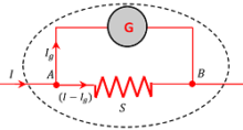
Therefore, remaining current flowing through the shunt will be \left ( I - I_g \right )
Since, ( G ) and ( S ) are connected in parallel so the voltage across them is same.
Therefore, \quad I_g G = \left ( I - I_g \right ) S
Or, \quad S = \left ( \frac {I_g}{I - I_g} \right ) G ……. (1)
- This is the required value of shunt resistance to be added in parallel to the coil of meter.
- The converted device can be used safely as ammeter of range ( 0 ) to ( I ) ampere.
Effective Resistance of Ammeter
Total effective resistance ( R_{e} ) of ammeter becomes –
\left ( \frac {1}{R_{e}} \right ) = \left ( \frac {1}{G} \right ) + \left ( \frac {1}{S} \right ) = \left ( \frac {G + S}{GS} \right )
Or, \quad ( R_{e} ) = \left ( \frac {GS}{G + S} \right ) ……. (2)
Since ( G >> S ) , so \left ( G + S \right ) \simeq G
Hence, \quad ( R_{e} ) = \left ( \frac {GS}{G} \right ) = S
- Thus an ammeter is a low resistance device.
- Resistance of an ideal ammeter is zero.
- An ammeter is always connected in series of in the circuit of which current has to measure.
Increasing the Range of Ammeter
Consider that an ammeter is capable of measuring a maximum current ( I_1 ) . We have to modify it so that it become capable of measuring a current up to ( I_2 ) .
Let, \quad \left ( \frac {I_2}{I_1} \right ) = n
Now, from equation (1) for an ammeter, we have –
S = \left ( \frac {I_g}{I - I_g} \right ) G ……. (1)
Since, maximum allowable current through the ammeter coil is ( I_1 ) , we can replace ( I_g ) \ \text {and} \ ( I ) in equation (1) by ( I_1 ) \ \text {and} \ ( I_2 ) respectively.
Therefore, \quad S = \left ( \frac {I_1}{I_2 - I_1} \right ) G
Or, \quad S = \left [ \frac {G}{\left ( \frac {I_2}{I_1} - 1 \right )} \right ] = \left ( \frac {G}{n - 1} \right ) ………. (3)
Hence, amount of shunt resistance \left [ S = \left ( \frac {G}{n - 1} \right ) \right ] that should be added in parallel to the coil of ammeter to increase its capacity.
Voltmeter
A voltmeter is an instrument used to measure the potential difference across the two ends of a circuit element.
Use of Galvanometer as a Voltmeter
- If we connect a simple galvanometer in parallel to a circuit to measure voltage, it will draw some current from circuit and hence potential difference between the points as recorded by the galvanometer will not be accurate.
- For accurate measurement of the potential difference, it is essential that the current between the two points of measurement should remain the same after connecting the measuring device.
- This is only possible if the resistance of the measuring device is very high or infinite, so that it may not draw any current.
- Hence, to measure potential difference, a galvanometer is modified and converted into a device whose resistance is very large.
Conversion of Galvanometer into Voltmeter
A galvanometer can be converted into a voltmeter by connecting a large resistance in series to the galvanometer.
Consider that –
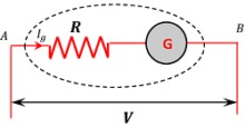
- ( R ) is the resistance connected in series to a galvanometer of coil resistance ( G )
- ( V ) volt is the potential difference to be measured by the voltmeter.
- ( I_g ) is the current flowing in the circuit corresponding to which the voltmeter gives the full scale deflection.
Now, potential difference between points A and B is given by –
V = I_g R + I_g G
Or, \quad V = I_g \left ( R + G \right )
Therefore, \quad ( R + G ) = \left ( \frac {V}{I_g} \right )
Or, \quad R = \left ( \frac {V}{I_g} \right ) - G ……… (1)
Hence, amount of resistance \left [ R = \left ( \frac {V}{I_g} \right ) - G \right ] should be added in series to the coil of Galvanometer to work as a Voltmeter.
Effective Resistance of Voltmeter
Effective value of resistance of a voltmeter is given by –
( R_{e} ) = ( R + G ) which is very high.
- Thus, voltmeter is a high resistance device.
- Resistance of an ideal voltmeter is infinite.
- A voltmeter is always connected in parallel to the element across which voltage has to measure.
See numerical problems based on this article.