What is a Moving Coil Galvanometer?
A moving coil galvanometer is a device used to detect or measure small electric current flowing in an electric circuit.
- It works on the principle that, a current carrying loop or coil experiences a magnetic force which produces a torque in the loop, when it is placed in a magnetic field.
- Most of the other electrical instruments like Voltmeter, and Ammeter etc. work on this principle.
Use of Galvanometer
- A Galvanometer is used to detect electric current in a circuit e.g., Wheatstone Bridge.
- It can be converted into an Ammeter by connecting a low resistor (i.e. shunt) parallel to it.
- It can be converted to a Voltmeter by connecting a high resistance in series with it.
- A Galvanometer can be used as an Ohmmeter ( Resistance measuring device ) by making special arrangements to it.
Advantages of Moving Coil Galvanometer
- The magnetic field produced by the cylindrical magnet of the galvanometer is very strong as compared to the Earth’s magnetic field. Hence, Earth’s magnetic field does not affect the working of a moving coil galvanometer.
- A galvanometer can be made extremely sensitive so that even a very feeble current in the circuit can be detected.
- Since deflection of the coil is directly proportional to the current so a linear scale can be used.
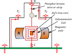
Construction of Moving Coil Galvanometer
Construction of a moving coil galvanometer is shown in figure.
- It consists of a coil wound on a brass frame.
- The coil is suspended between the poles N \ \text {and} \ S of a cylindrical magnets.
- The coil or solenoid is suspended with a movable torsion head H by a strip or wire made of phosphor bronze which acts as path for the current to the coil.
- End of the wire is connected to the terminal T_2 of the galvanometer.
- The other end of the coil is connected to a light spring ( S ) which is finally connected to the terminal T_1 . The spring exerts a very small restoring torque on the coil.
- A soft iron core is placed within the frame of the coil.
- A plane circular mirror M is attached on the wire or strip to note the deflection of the coil using lamp and scale arrangement.
- The whole system is enclosed in a non-metallic or wooden case to avoid disturbance due to air.
Working of Moving Coil Galvanometer
Consider that –
- Intensity of magnetic field is ( B )
- Current flowing through the coil is ( I )
- Number of turns in the coil is ( N )
- Length of coil is ( l )
- Breadth of the coil is ( b )
- Angle between normal of the plane of coil with the direction of the magnetic field is ( \theta ) .
- Restoring torque per unit twist of restoring spring ( S ) is ( k ) .
A galvanometer is connected in series in a circuit. When current flows in the circuit, the same current flows through the coil of galvanometer and it experiences a torque.
- From the article Torque on a current loop, magnitude of torque in the galvanometer coil will be –
\tau_N = N I A B \sin \theta
- In a galvanometer, cylindrical poles are used to produce radial magnetic field. In a radial magnetic field, filed lines are parallel to the plane of the coil of galvanometer. Therefore, ( \theta = 90 \degree ) .
Hence, maximum deflecting torque is developed in the coil which is given by –
\tau = N I A B …….. (1)
When the coil gets deflected the restoring spring ( S ) is twisted and a restoring torque is developed in it.
Let, the deflection in the coil is ( \phi ) , then restoring torque in the restoring spring will be –
{\tau}' = ( k ) \phi …….. (2)
For equilibrium of the coil, \quad \text {Deflecting torque} = \text {Restoring torque}
- Therefore, \quad N I A B = ( k ) \phi ……… (3)
Or, \quad I = \left ( \frac { k \phi }{ N A B } \right ) ……… (4)
Galvanometer Constant
Current through the coil of a galvanometer is given by the expression –
I = \left ( \frac { k \phi }{ N A B } \right )
= \left ( \frac { k }{ N A B } \right ) ( \phi )
In this expression ( k ), \ ( N ), \ ( A ) \ \text {and} \ ( B ) are design features of a galvanometer.
Therefore, term \left ( \frac { k }{ N A B } \right ) may be taken as a constant for a given galvanometer. This constant is called Galvanometer constant. It is denoted by ( G )
- Therefore, galvanometer constant is given by –
G = \left ( \frac { k }{ N A B } \right )
Hence, equation (4) for a galvanometer reduces to –
I = G \phi
- Therefore, \quad I \ \propto \ \phi
Thus, deflection of the coil is directly proportional to the current flowing through it. Hence, we can use a linear scale in the galvanometer to detect the current in a circuit.
Sensitivity of Galvanometer
A galvanometer is said to be sensitive if a small current flowing through the coil of galvanometer produces a large deflection in the galvanometer.
A galvanometer should be sensitive in following ways –
- Current sensitivity.
- Voltage sensitivity.
Current Sensitivity
The current sensitivity of a galvanometer is defined as the deflection produced in the galvanometer per unit current flowing through it. A galvanometer should be sufficiently sensitive to the current so that it may capable to response when a very low current flow through the coil.
\text {Current sensitivity} = \left ( \frac {\text {Deflection}}{\text {Current}} \right )
- To measure a current in a circuit, a galvanometer is connected in series to the circuit.
Therefore, current through coil will be –
I = \left ( \frac { k \phi }{ N A B } \right ) ……… (4)
Therefore, Current sensitivity of the galvanometer will be –
\left ( \frac {\phi}{I} \right ) = \left [ \frac {\phi \left (NAB \right )}{k \phi} \right ]
Or, \quad \left ( \frac {\phi}{I} \right ) = \left ( \frac {NAB}{k} \right )
- Current sensitivity of galvanometer can be increased by –
- Increasing the magnetic field ( B ) by use of a strong permanent horse shoe magnet.
- By increasing the number of turns ( N ) of coil only up to a certain limit. Because increase in number of turns will also increase the resistance of galvanometer coil and after certain limit the resistance will become considerably high and galvanometer will become less sensitive.
- Increasing the area ( A ) of the coil. But this will make the galvanometer bulky and ultimately less sensitive.
- Decreasing the value of restoring force constant ( k ) by using a flat strip spring of phosphor-bronze instead of a circular spring because the value of ( k ) is small for a flat strip in comparison to a round wire.
Voltage Sensitivity
The voltage sensitivity of a galvanometer is defined as the deflection produced in the galvanometer per unit voltage applied to it. A galvanometer should be sufficiently sensitive to the voltage so that it may capable to response when a very low voltage is applied across the coil.
\text {Voltage sensitivity} = \left ( \frac {\text {Deflection}}{\text {Voltage}} \right )
- To measure voltage in a circuit element, a galvanometer is connected in parallel to the element in the circuit.
Therefore, voltage sensitivity of a galvanometer will be –
\left ( \frac {\phi}{V} \right ) = \left ( \frac {\phi}{IR} \right )
Here, ( R ) is the resistance of the coil.
- Current through a galvanometer coil is given by –
I = \left ( \frac { k \phi }{ N A B } \right ) ……… (4)
Or, \quad \phi = \left ( \frac { I N A B }{ k } \right )
- Therefore, voltage sensitivity will become –
\left ( \frac {\phi}{V} \right ) = \left ( \frac {INAB}{Vk} \right )
Or, \quad \left ( \frac {\phi}{V} \right ) = \left ( \frac {NAB}{kR} \right )
- Voltage sensitivity of a Galvanometer can be increased by –
- Increasing the number of turns ( N ) of coil.
- Enhancing the magnetic field intensity ( B )
- Increase the area of coil ( A )
- Reducing the stiffness of spring ( k ) and
- Decreasing the resistance of coil ( R )
See numerical problems based on this article.