What are Electric Field Lines?
Electric field lines are straight or curved imaginary lines in the region of electric field of a source charge such that the tangent at any point on the field line gives the direction of the electric field at that point.
These are the graphical representation of existence of an electric field.
Properties of Electric Field Lines of single Point Charge
Electric field lines of a single point charge have the following properties –
- If we place a unit positive charge ( + q_0 ) in the electric field of a positive source charge ( + q ) , it will experience a repulsive force radially outward as shown in figure (a).
- Thus the field lines for a positive charge are represented by straight lines originating from the centre of point charge.
- These field lines are called as diverging field lines.
In similar manner –
- If we place a unit positive charge ( + q_0 ) in the electric field of a negative charge ( - q ) , it will experience a attractive force radially inward as shown in figure (b).
- Thus the field lines for a negative charge are represented by straight lines converging at the centre of point charge.
- These field lines are called as converging field lines.
- The spreading of the field lines with distance from the charge indicates that the magnitude of the electric field intensity decrease with increase in distance from the charge.
Field lines for point charges are shown in figure (a) and (b).
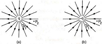
- The spreading of the field lines with distance from the charge indicates that the magnitude of the electric field intensity decrease with increase in distance from the charge.
- Consider about two points P_1 and P_2 in above figures. If we draw equal small areas through P_1 and P_2 perpendicular to the lines, the number of lines passing through the area at P_1 will be more.
- This indicates that the electric field intensity at point P_1 is more than at point P_2 .
- Hence, density of field lines at a point represents the magnitude of electric field at that point.
Properties of Electric Field Lines of two Point Charges
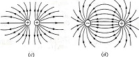
Field lines for a pair of charges is shown in figure.
- Electric field lines for two equal positive point charges is shown in figure (c)
- Field lines for two equal but unlike charges is shown in figure (d)
- Electric field lines originate from positive charge and terminate at negative charge.
- Two electric field lines never cross to each other.
- Electric field lines do not pass through a conductor because the interior of a conductor is free from the influence of the electric field.
Electric Flux
The electric flux linked with any surface is defined as the total number of electric field lines passing through that surface.
Consider about a plane surface of area ( S ) kept perpendicularly in the electric field ( \vec {E} ) as shown in figure (A).
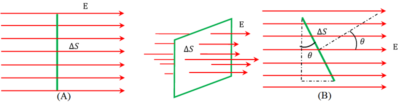
Since, electric field lines are normal to the surface of area ( S ) then electric flux linked to the surface is given by –
\phi = E S
Thus, electric flux may be defined as the product of the magnitude of the electric field ( E ) and the surface area ( S ) perpendicular to the direction of electric field.
If the surface is kept in such a way that its normal makes an angle ( \theta ) in positive direction to the direction of electric field ( \vec {E} ) as shown in figure (B) then effective area normal to the field will be ( S \cos \theta )
Therefore, total flux linked to the surface will be –
\phi = E S \cos \theta
Conductor kept in an Electric Field
A conductor or a conducting material contains a large number of free electrons. When, the conductor is placed in an electric field ( \vec {E_0} ) , each electron experience electrostatic force ( \vec {F} = - e \vec {E_0} ) in a direction opposite to the direction of the applied field.
This force causes free electrons to move in the conductor in a direction opposite to the direction of applied electric field as shown in figure.
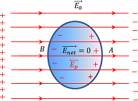
Thus, side A of the conductor become positively charged due to transfer of free electrons to the side B. Also side B of the conductor becomes negatively charged.
Therefore, side A of the conductor has less electrons as compared to the side B. This re-distribution of charges will create its own electric field on the surface called induced electric field ( \vec {E_p} ) .
This induced electric field is equal in magnitude of the applied electric field ( \vec {E_0} ) but acts in a opposite direction.
Hence, net electric field ( \vec {E_{net}} ) in the interior of the conductor becomes zero.
Effects of Induced Electric Field
The induced electric field in a conducting material has following effects.
- Net electric field ( \vec {E_{net}} ) in the interior of the conductor becomes zero.
- Electric field just outside of the charged conductor is perpendicular to the surface of the conductor.
- Net charge in the interior of the conductor becomes zero. (This can be obtained by application of Gauss laws.
- Charge resides only on the outer surface of the conductor.
- Electric potential is constant for the entire conductor.
- Surface charge density may be different at different points on surface depending upon the shape of cross section of conductor.
For a conical shaped conductor, surface charge density near the apex of cone will be higher due to less area.
Electrostatic Shielding
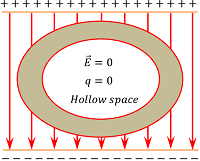
The method of protecting a region from the effect of electric field is called electrostatic shielding.
Sensitive instruments and appliances are affected seriously with strong electrostatic fields. Their working suffers and they may not work properly under electric fields.
We have learnt that, inside the hole of a hollow conductor, the intensity of electric field is zero. Therefore, electrostatic shielding can be achieved by protecting and enclosing the sensitive instruments inside a hollow conducting body as shown in figure.
The inner side of the hollow conducting body remains unaffected by the presence of external field and thus prevent the instruments from any damages due to electrostatic forces.
See numerical problems based on this article.