What is a Venturimeter?
Venturimeter is a rate of flow measuring device which is directly mounted on the pipeline through which a liquid flows. In this device, a converging section of a pipe is used to increase the flow velocity which results a corresponding decrease in pressure from which the flow rate of the fluid is calculated. The device uses an U-Tube manometer which reads the drop in pressure. The device is based on Bernoulli’s equation.
Therefore, a venturimeter is an apparatus meant for measuring the flow quantity or discharge of a liquid flowing through a pipeline. It works on the principle of Bernoulli’s theorem.
Construction of a Venturimeter
Simplest form a venturimeter is consists of following sections.
- Convergent cone.
- Throat.
- Divergent cone.
Construction and working principle of a venturimeter is shown in figure below.
Convergent cone
It is a short pipe converging section from pipe diameter ( d_1 ) to a smaller diameter ( d_2 ) .
- Convergent cone is also called as Inlet of venturimeter.
- Slope of the converging sides is kept in ratio of ( 1 : 4 ) \ \text {to} \ ( 1 : 5 ) to avoid separation of liquid flow.
Throat
Convergent cone leading to a throat. It is a small portion of circular pipe in which the diameter ( d_2 ) is kept constant for a small length.
Divergent cone
Throat leads to a diverging cone which diverges from throat diameter ( d_2 ) to larger pipe diameter ( d_1 ) .
- Divergent cone is also known as Outlet of venturimeter.
- The length of the divergent cone is kept about 3 \text {to} 4 times more than that of the length of convergent cone to avoid separation of liquid flow.
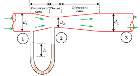
The liquid while flowing through the venturimeter is accelerated between the sections 1 and 2 of the convergent cone. As a result of the acceleration, the velocity of liquid at section 2 becomes higher than that at section 1. This increase in velocity, results in decrease of the pressure at section 2 considerably.
If the pressure head at the section 2 i.e., at throat falls below the separation head (which is ( 2.5 \text {m} ) of water) then there will be a tendency of separation of the liquid flow. In order to avoid this tendency of separation, the ratio of the diameter of throat and the pipe i.e. \left ( \frac {d_1}{d_2} \right ) is kept fixed. This ratio varies from \left ( \frac {1}{3} \ \text {to} \ \frac {1}{2} \right ) .
The liquid, while flowing through the venturimeter is decelerated (i.e., retarded) between the sections 2 and 3 in the divergent cone. As a result of this retardation the velocity of liquid decreases which consequently increases the pressure.
There is a possibility of liquid to separate from the walls of the diverging section of venturimeter due to rapid increase of pressure and boundary layer effects. To avoid this separation, the divergent cone is made sufficiently longer about 3 \text {to} 4 times longer than the convergent cone. This also reduces the frictional losses.
Tubes are provided to connect Piezometer tubes or U tube manometer between entrance section 1 and throat section 2. These tubes are meant for measurement of difference of pressures between sections 1 and 2.
Working Principle of Venturimeter
The working of Venturimeter is based on Bernoulli’s theorem. Consider about the sections 1 and 2 corresponding to the entrance and throat sections respectively.
As the liquid flows through the venturimeter, the velocity at the throat section increases due to the decrease in the cross sectional area of flow. This increase in velocity is accompanied by a consequent decrease of pressure.
Let –
- ( a_1 ) is the area of entrance section 1.
- ( a_2 ) is area of throat section 2.
- ( v_1 ) is velocity of liquid at entrance section.
- ( v_2 ) is velocity of liquid at throat section.
- ( p_1 ) is pressure intensity at entrance section 1.
- ( p_2 ) is pressure intensity at throat section 2.
- ( Q ) is discharge through the venturimeter.
- ( w ) is specific weight of liquid flowing through the pipeline.
Assume that the meter is horizontally placed and energy losses are negligible.
So, \quad Z_1 = Z_2
We can apply Bernoulli’s theorem to the sections 1 and 2. Thus we get –
\frac {p_1}{w} + \frac {v_1^2}{2g} = \frac {p_2}{w} + \frac {v_2^2}{2g}
Or, \quad \frac {v_2^2}{2g} - \frac {v_1^2}{2g} = \frac {p_1}{w} - \frac {p_2}{w}
Let, \quad \frac {p_1}{w} - \frac {p_2}{w} = h \quad It is called Venturi head.
- Therefore, \quad \left ( \frac {v_2^2}{2g} - \frac {v_1^2}{2g} \right ) = h
Or, \quad v_2^2 - v_1^2 = 2 g h
But from equation of continuity, we have \quad Q = a_1 v_1 = a_2 v_2
- Therefore, \quad v_2 = \left ( \frac {a_1}{a_2} \right ) v_1
Or, \quad \left ( \frac {a_1^2}{a_2^2} \right ) v_1^2 - v_1^2 = 2 g h
So, \quad \left [ \frac {a_1^2 - a_2^2}{a_2^2} \right ] v_1^2 = 2 g h
Or, \quad v_1 = \left [ \frac {a_2}{\sqrt {a_1^2 - a_2^2}} \right ] \sqrt {2 g h}
But \quad Q = a_1 v_1
- Therefore, \quad Q = \left [ \frac {a_1 a_2}{\sqrt {a_1^2 - a_2^2}} \right ] \sqrt {2 g h}
Coefficient of Discharge
Above equation gives the discharge under ideal conditions assuming no losses. In the actual conditions a loss of energy head occurs and the actual discharge is slightly less than the above value.
Hence, for the actual case, rate of flow or discharge –
Q = \left [ \frac {C_d a_1 a_2}{\sqrt {a_1^2 - a_2^2}} \right ] \sqrt {2 g h}
Where, ( C_d ) is called coefficient of discharge.
In the above relation, the ratio \left ( \frac {a_1}{a_2} \right ) = K is called Venturi constant.
By rearranging the discharge equation, we get –
Q = C_d \left [ \frac {a_1}{\sqrt {K^2 - 1}} \right ] \sqrt {2 g h}
- The discharge equation in this form is found very convenient to use.
What is an Orifice Meter?
An Orifice Meter is also a rate of flow measuring device which is directly mounted on the pipeline through which a liquid flows. In this device, a plate having a circular orifice is inserted in the pipeline. The orifice plate is used to increase the flow velocity which results a corresponding decrease in pressure from which the flow rate of the fluid is calculated. The device uses an U-Tube manometer which reads the drop in pressure. The device is based on Bernoulli’s equation.
Therefore, an orifice meter is used to measure the flow rate or discharge of liquid in a pipeline. It works on the principle of Bernoulli’s theorem.
Construction of an Orifice Meter
An orifice meter, in its simplest form is consists of a plate having a sharp edged circular hole known as an orifice. This plate is fixed inside a pipe as shown in figure.
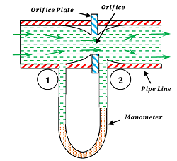
A mercury manometer is inserted to know the difference of pressures between the sections 1 of pipe and section 2 of the throat or orifice.
Consider that –
- ( a_1 ) is area of pipe or entrance section 1 of orifice meter.
- ( v_1 ) is velocity of liquid at entrance section.
- ( p_1 ) is pressure intensity at entrance section 1.
- ( Q ) is discharge through the orifice meter.
- ( w ) is specific weight of liquid flowing through the pipeline.
- h = is reading of the mercury manometer.
And a_2, \ v_2, \ p_2 are the corresponding values at throat section 2.
Working of Orifice Meter
Now, applying Bernoulli’s equation for sections 1 and 2 we get –
Z-1 + \frac {p_1}{w} + \frac {v_1^2}{2g} = Z_2 + \frac {p_2}{w} + \frac {v_2^2}{2g}
Assuming that the pipe is horizontal placed, we have \quad Z_1 = Z_2
- Therefore, \quad \left ( \frac {v_2^2}{2g} - \frac {v_1^2}{2g} \right ) = \left ( \frac {p_1}{w} - \frac {p_2}{w} \right )
But \quad \left ( \frac {p_1}{w} - \frac {p_2}{w} \right ) = h Reading of Manometer.
- Therefore, \quad h = \left ( \frac {v_2^2}{2g} - \frac {v_1^2}{2g} \right )
Or, \quad \left ( v_2^2 - v_1^2 \right ) = 2 g h
But from equation of continuity, we have \quad Q = a_1 v_1 = a_2 v_2
- Therefore, \quad v_2 = \left ( \frac {a_1}{a_2} \right ) v_1
Or, \quad \left ( \frac {a_1^2}{a_2^2} \right ) v_1^2 - v_1^2 = 2 g h
So, \quad \left [ \frac {a_1^2 - a_2^2}{a_2^2} \right ] v_1^2 = 2 g h
Or, \quad v_1 = \left [ \frac {a_2}{\sqrt {a_1^2 - a_2^2}} \right ] \sqrt {2 g h}
But \quad Q = a_1 v_1
- Therefore, \quad Q = \left [ \frac {a_1 a_2}{\sqrt {a_1^2 - a_2^2}} \right ] \sqrt {2 g h}
This is the discharge under ideal conditions. In the actual cases a loss of energy head occurs and the actual discharge is slightly less than the above value. If ( C_d ) is the coefficient of orifice meter. Then –
Q = \left [ \frac {C_d a_1 a_2}{\sqrt {a_1^2 - a_2^2}} \right ] \sqrt {2 g h}
What is a Pitot Tube?
A pitot tube is a device which is directly mounted in the pipeline in which a liquid flow. This is used to find the velocity of flow of the liquid in the pipeline.
Therefore, a pitot tube is an instrument to determine the velocity of flow at the required point in a pipe or stream.
In its simplest form, a pitot tube is consists of a glass tube bent through ( 90 \degree ) as shown in figure.
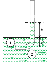
The lower end of the tube faces the direction of the flow as shown in figure. The liquid rises up in the tube due to the pressure exerted by the flowing liquid. By measuring the rise of liquid in the tube, we can find out the velocity of the liquid flow. Let –
- ( h ) is height of the liquid in the pitot tube above free liquid surface.
- ( H ) is depth of the tube in the liquid.
- ( v ) is velocity of the liquid.
Applying Bernoulli’s equation for the sections 1 and 2 we get –
H + \frac {v^2}{2g} = H + h
Or, \quad h = \left ( \frac {v^2}{2g} \right )
- Therefore, \quad v = \sqrt {2gh}
It has been experimentally found that –
- If the pitot tube is placed with its nose facing side way in the flow, there will be no rise of the liquid in the tube.
- But if a pitot tube is placed with its nose facing down stream, the liquid level in the tube will be depressed by an amount equal to ( h ) , such that –
h = \sqrt {\frac {v^2}{2g}}
Where ( v ) is the velocity of the liquid flow.