What is a Pulley System?
A pulley or sheave is a disc like object which has a groove on its rim. In this groove, a flexible rope or chain is wound to apply a pulling force or effort. A group of two or more pulleys working together, is called a pulley system.
- The pulley rotates on a cylindrical rod called axle or spindle.
- A pulley used for lifting water buckets from well is a very common example.
Use of Pulley
A pulley system is used for following purposes –
- A simple system uses one pulley and is used to change the direction of applied effort or motion.
- A simple pulley is used for lifting water buckets from a well.
- A compound system of pulleys uses more than one pulley and is used for lifting of heavy loads at considerable large height.
- It is used for erection and installation of heavy machinery on structural frames, girders etc.
Types of Pulley
Pulley is classified into two types according to the rope or chain used to apply effort. These are –
- Rope pulley – (1) In this system, a rope is wound around rim of pulley. (2) It generally contains one pulley in the system. (3) Its mechanical advantage is low.
- Chain pulley – (1) In this system, a chain is wound around rim of pulley. (2) It generally contains more than one pulley. (3) It has high mechanical advantage as compared to rope system. (4) Nomenclature of the system is done based on the number of pulleys in the system.
Pulley is classified into four types according to the number of pulleys in the system. These are –
- Simple pulley system – (1) This system consists of only one pulley. (2) Its mechanical advantage is ( 1 ) due to presence of one pulley. (3) It is the simplest form of pulley system. (4) It has not of much importance. (5) It is used to change the direction of applied effort or motion.
- Compound pulley system – (1) This system uses more than one pulley. (2) Its mechanical advantage is more than ( 1 ) due to presence of more pulleys. (3) Its nomenclature is based on the number of pulleys. Such as – System of two pulleys, System of three pulleys etc. (4) A two pulley system is the simplest form of a compound system.
- Pulley Blocks – (1) In a pulley block system, more number of pulleys are mounted on the same spindle which rotate with their individual speeds. (2) One set of pulley on one spindle is called a block. (3) This system is used to get large mechanical advantage.
- Differential Pulley – (1) In this pulley system, two number of pulleys are mounted on the same spindle which rotate with their individual speeds in opposite directions. (2) An endless chain passes over these two pulleys. (3) This system is used to get higher mechanical advantage.
Velocity Ratio of a Pulley system
Velocity ratio of a machine is defined as the ratio of distance moved by effort to the distance moved by the load.
Therefore, \quad \text {Velocity Ratio} = \left ( \frac {\text {Distance moved by effort}}{\text {Distance moved by load}} \right )
Simple pulley system –
- A simple pulley consists of one pulley.
- In this system, \quad \text {Distance moved by effort} = \text {Distance moved by load}
- Therefore, Velocity ratio of this system is 1
Two pulley system –
- This system contains two pulleys.
- In this system, \quad \text {Distance moved by effort} = 2 \times \ \text {Distance moved by load}
- Therefore, Velocity ratio of a this system is 2
Thus, we can say that – “Velocity ratio of a pulley system is equal to the number of pulleys in the system.”
Mechanical Advantage of Pulley system
Mechanical advantage of a machine is defined as the ratio of Load lifted to the Effort applied.
Therefore, \quad \text {Mechanical Advantage} = \left ( \frac {\text {Load}}{\text {Effort}} \right )
Example –
To understand the mechanical advantage of a pulley system, consider an example of a system consisting of two pulleys.
- In this system, effort or pull ( P ) is applied at one end of a rope which successively passes over two pulleys.
- The other end of rope is tied with the axle of the first pulley ( upper pulley ).
- The load ( W ) is hanged with a linkage attached with the axle of second pulley ( lower pulley ).
- If the distance moved by effort is ( x ) then the distance moved by load will be \left ( \frac {x}{2} \right ) .
- Then work done by the applied pull is \left ( P \times x \right ) and work output in lifting the load is \left ( W \times \frac {x}{2} \right )
Therefore, in absence of friction, by principle of conservation of energy –
\left ( P \times x \right ) = \left ( W \times \frac {x}{2} \right )
So, \quad \left ( \frac {W}{P} \right ) = \left ( \frac {2x}{x} \right )
Or, \quad MA = 2
Therefore, mechanical advantage of a system of two pulleys is 2 .
In this way, we can say that – “In absence of friction, mechanical advantage of a system of pulleys is equal to the number of pulleys in the system.”
Importance of number of ropes in Pulley system
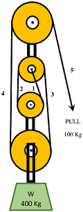
Consider about a system of four pulleys as shown in figure.
- This system is a combination of four number of pulleys.
- Hence, its velocity ratio is ( 4 )
- Due to presence of four pulleys in the system, its mechanical advantage is also ( 4 )
Therefore, to find velocity ratio and mechanical advantage of a compound pulley system, another simple process is as follows –
- Count the number of ropes in the system which support load ( W ) .
- In figure, rope numbers 1, \ 2, \ 3 \ \text {and} \ 4 are used to support load. These ropes are called load rope.
- Rope number ( 5 ) is used to apply effort. Hence it is not counted. This rope is called effort rope.
- This system has velocity ratio of ( 4 ) . Its mechanical advantage is also ( 4 )
Therefore, Velocity ratio of a pulley is equal to the number of ropes used to support the load.
Pulley Blocks
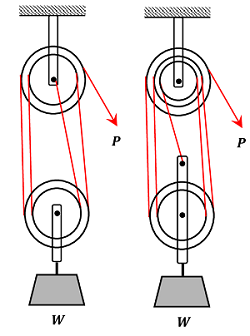
In a pulley block system, more number of pulleys are mounted on one axle which are free to rotate with their own speeds. One set of pulleys is called a block.
Two types of pulley block system are shown in figure.
- In the first figure, each of upper block and lower block contains ( 2 ) pulleys.
- So, to lift load ( W ) through unit distance, each portion of the ropes attached with load block should be shortened by unit length.
- There are ( 4 ) number of ropes attached with lower load block.
- So, four unit length of rope must be pulled off by the effort ( P ) .
So, the velocity ratio of the system is ( 4 ) .
- In the second figure, the upper block contains ( 3 ) pulleys and the lower block has ( 2 ) pulleys.
- Lower block is connected with load ( W ) and number of ropes connected with this is ( 5 ) .
So, the velocity ratio of the system is ( 5 ) .
Differential Pulley Block
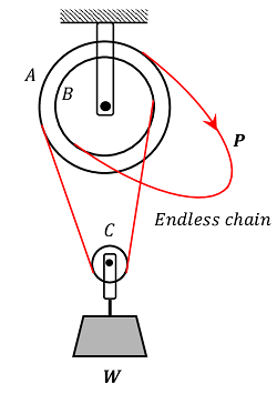
A Weston’s Differential Pulley block system is shown in figure.
- It consists of two pulleys A \ \text {and} \ B mounted on common spindle.
- An endless chain passes over pulley A , then under the snatch block C carrying the load ( W ) and finally passes over pulley B .
- The effort ( P ) is applied to that part of the chain which passes over pulley A .
- The pulleys are provided with teeth to prevent the slipping of the chain.
Let, the radii of pulleys A \ \text {and} \ B are respectively r_1 \ \text {and} \ r_2 and radius ( r_1 > r_2 ) .
- In one revolution of pulley A , length ( 2 \pi r_1 ) of chain passes over the pulley A towards the right while a length ( 2 \pi r_2 ) passes over the pulley B towards the left.
- Hence, the portion of the chain between A \ \text {and} \ B carrying the load is decreased in length by the amount [ 2 \pi ( r_1 - r_2 )]
- Therefore, ( W ) is lifted through a height [ \pi ( r_1 - r_2 ) ] from its initial position.
- The distance moved by the effort is ( 2 \pi r_1 ) .
Therefore, Velocity ratio of this system will be –
\left [ \frac { 2π r1 }{ π ( r1 - r2 ) } \right ] = \left [ \frac { 2 r1 }{ ( r1 - r2 ) } \right ]
The number of teeth on the pulleys are proportional to the radius of the pulleys. Let, ( N_1 \ \text {and} \ N_2 ) are the number of teeth on the pulleys.
Then, velocity ratio will be –
\left ( \frac { 2N1 }{ ( N1 - N2 ) } \right )