What is Self Induction in Coils?
Self induction is the property of a coil by virtue of which it opposes the change (i.e. growth or decay) of current flowing through it.
To understand this phenomenon, consider about a coil (an inductor) connected to a battery ( E ) through a key ( K ) as shown in figure.
When the key ( K ) is closed, the current starts flowing in the coil. Due to increase in current in the coil, the magnetic field and hence magnetic flux linked around the coil also increases. This brings a change in magnetic flux linked with the coil. As a result of this change, induced EMF is set up in the coil. According to Lenz law, the direction of induced EMF is such that it opposes the growth of current in the coil. This delays the current to acquire the maximum value in the coil.
Similarly when the key ( K ) is opened, the current in the coil starts decreasing. So, the magnetic flux linked with the coil also decreases. As a result, again induced EMF is set up in the coil by itself. According to Lenz law, the direction of induced EMF is such that, it opposes the decay of current in the coil. This delays the current to acquire zero value in the coil.
This property of a coil which opposes the growth or decay of the current in a coil or circuit is called Self Induction.
Self Induction is also known as Inertia of electricity, because it opposes the growth or decay of change in electric current.
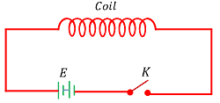
Illustration of Self Induction
Phenomenon of self induction can be demonstrated by the following experiment –
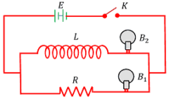
Two lamps B_1 and B_2 are connected in parallel to each other. Lamp B_1 is connected through the ohmic resistor ( R ) and the lamp B_2 is connected through a inductive coil ( L ) . This combination is connected across a battery ( E ) and a key ( K ) respectively as shown in figure.
When key is closed –
It is observed that lamp B_1 glows immediately with full brightness but lamp B_2 takes time to glow to its full brightness. This happens because, when current flows through the coil an EMF is induced in it which opposes the growth of current in the circuit. Hence, the glow of the lamp B_2 is slow. But no induced EMF is produced in the resistor. Hence, the lamp B_1 receives maximum current soon and it glows at once.
When the key is opened –
Lamp B_1 stops glowing instantly but the lamp B_2 takes some time. This happens because, when current begins to decrease through the coil, again EMF is induced in it which opposes the decay of current in the circuit. But, no induced EMF is induced in the resistor. Hence, the lamp B_1 diminishes instantly.
Self Inductance
Let, at any instant a current ( I ) flows through a coil. Then the magnetic flux linked with the coil is proportional to the current.
\phi \propto I
So, \quad \phi = L I ……… (1)
Here, ( L ) is constant of proportionality known as Coefficient of Self Induction or Self Inductance.
If, ( I = 1 ) , then from equation (1) we have –
L = \phi ……… (2)
Thus, coefficient of Self Induction or Self Inductance of a coil is defined as the magnetic flux linked with the coil when unit current flows through it.
From Faraday’s laws of electromagnetic induction, induced EMF in a coil is –
\epsilon = - \left ( \frac {d \phi}{dt} \right )
Putting the value of \phi from equation (1), we will get –
\epsilon = - \left ( \frac {d}{dt} \right ) ( L I )
= - L \left ( \frac {dI}{dt} \right ) ………. (3)
If, the rate of decrease of current in the coil is unit, then –
- \left ( \frac {dI}{dt} \right ) = 1
Thus, \quad L = \epsilon
Therefore, coefficient of Self Induction or Self Inductance of a coil is also defined as the induced EMF produced in the coil when the rate of decrease of current is unity.
Unit of Self Inductance
SI unit of Self Inductance is henry.
Since, \quad \epsilon = - L \left ( \frac {dI}{dt} \right )
So, \quad L = \left [ \frac {\epsilon}{\left ( \frac {dI}{dt} \right ) } \right ]
Therefore, 1 \ \text {Henry} = \left [ \frac {1 \ \text {Volt}}{1 \ \text {Ampere second}^{-1}} \right ] = 1 \ \text {V-s A}^{-1}
Also, \quad L = \left ( \frac {\phi}{I} \right )
Therefore, 1 \ \text {Henry} = \left ( \frac {1 \ \text {Weber}}{1 \ \text {Ampere}} \right ) = 1 \ \text {Wb A}^{-1}
Self Inductance of a coil
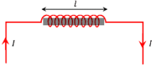
Consider a long solenoid of length ( l ) , area ( A ) , number of turns per unit length ( n ) . Then, total number of turns in the solenoid will be –
N = n l
Let, ( I ) is the current flowing through solenoid. By Ampere’s circuital law the magnetic field of solenoid will be –
B = \mu_0 n I
Therefore, magnetic flux linked with one turn will be –
B \times A = \mu_0 n I A
Hence, total magnetic flux linked with the solenoid –
\phi = \mu_0 n I A \times nl = \mu_0 n^2 I A l ……… (1)
Also, if ( L ) is the Self Inductance of the coil, then –
\phi = LI ………. (2)
Comparing equations (1) and (2), we will get –
LI = \mu_0 n^2 I A l
So, \quad L = \mu_0 n^2 A l …….. (3)
= \mu_0 \left ( \frac {N}{l} \right )^2 A l
Therefore, \quad L = \mu_0 \left ( \frac {N^2}{l} \right ) A
When, the solenoid is wound on a rod made of a material of permeability ( \mu_r ) , then self inductance of the solenoid will be –
L' = \mu_0 \mu_r n^2 A l …….. (4)
= \mu_0 \mu_r \left ( \frac {N}{l} \right )^2 A l
= \mu_r \left [ \mu_0 \left ( \frac {N^2}{l} \right ) A \right ]
Therefore, \quad L' = \mu_r L
- Thus Self Inductance of a solenoid also depends upon the nature of core material.
- Hence, Self Inductance of a coil can be increased by inserting a suitable iron core.
Self Inductance of Coils in Series combination
Let, two coils of inductance ( L_1 ) \ \text {and} \ ( L_2 ) are connected in series as shown in figure.
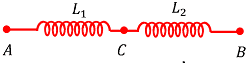
Assume that, ( \epsilon_1 ) \ \text {and} \ ( \epsilon_2 ) are the potential differences across the coils.
Total potential difference across points A and B will be –
\epsilon = \epsilon_1 + \epsilon_2 ……….. (1)
Rate of change of current in both the coils is same, so –
- L \left ( \frac {dI}{dt} \right ) = - L_1 \left ( \frac {dI}{dt} \right ) - L_2 \left ( \frac {dI}{dt} \right )
Or, \quad L = L_1 + L_2 ……….. (2)
Hence, equivalent inductance of two coils connected in series is equal to the sum of individual inductance of the coils.
Self Inductance of Coils in Parallel combination
Let, two coils of inductance ( L_1 ) and ( L_2 ) are connected in parallel as shown in figure.
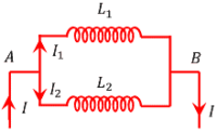
Assume that, ( I ) is the total current in the circuit and ( I_1 ) and ( I_2 ) are the flow of currents through the two coils. Then –
I = I_1 + I_2
Differentiating both sides with respect to ( t ) , we get –
\left ( \frac {dI}{dt} \right ) = \left ( \frac {dI_1}{dt} \right ) + \left ( \frac {dI_2}{dt} \right ) ……….. (3)
Let, ( L ) is the equivalent inductance of combination. Then –
\epsilon = - L \left ( \frac {dI}{dt} \right )
Or, \quad \left ( \frac {dI}{dt} \right ) = \left ( - \frac {\epsilon}{L} \right )
Since, the EMF across both of the coils is same –
Therefore, \quad \left ( \frac {dI_1}{dt} \right ) = \left (- \frac {\epsilon}{L_1} \right )
And, \quad \left ( \frac {dI_2}{dt} \right ) = ( - \frac {\epsilon}{L_2} )
Hence, equation (3) becomes –
\left ( \frac {\epsilon}{L} \right ) = \left ( - \frac {\epsilon}{L_1} \right ) - \left ( \frac {\epsilon}{L_2} \right )
= - \epsilon \left ( \frac {1}{L_1} + \frac {1}{L_2} \right )
So, \quad \left ( \frac {1}{L} \right ) = \left ( \frac {1}{L_1} + \frac {1}{L_2} \right ) = \left ( \frac {L_1 + L_2}{L_1L_2} \right )
Thus, \quad L = \left ( \frac {L_1L_2}{L_1 + L_2} \right )
Hence, reciprocal of equivalent inductance of two coils connected in parallel is equal to the sum of reciprocals of individual inductance of the coils.
Energy stored in an Inductor
Work done to maintain the maximum value of current through an inductor is stored as energy in the inductor. Therefore, energy stored in an inductor is given by the relation –
U = \left ( \frac {1}{2} \right ) L {I_0}^2
Here, ( I_0 ) is maximum value of current in the circuit.
And, for a solenoid, \quad B = \mu_0 n I_0 . Therefore, \quad I_0 = \left ( \frac {B}{\mu_0 n} \right )
Also, Self Inductance, \quad L = \mu_0 n^2 Al . Therefore, magnetic energy stored in a solenoid is will be –
U_m = \left ( \frac {1}{2} \right ) \left ( \mu_0 n^2 Al \right ) \left ( \frac {B}{\mu_0 n} \right )^2
= \left ( \frac {1}{2} \right ) \left ( \frac {B^2 Al}{\mu_0} \right )
= \left ( \frac {1}{2} \right ) \left ( \frac {B^2 V}{\mu_0} \right )
Magnetic Energy Density
Energy stored per unit volume of a solenoid is called magnetic energy density. It is denoted by ( \bar {U_{m}} ) .
Therefore, \quad \bar {U_{m}} = \left ( \frac {U_m}{V} \right )
= \left ( \frac {B^2}{2 \mu_0} \right )