What is a Bending Moment?
Various types of structural members are used for construction of industrial infrastructures to support various types of loads. The horizontally placed structural members are called beams. Different type of beams are used in structures for different purposes depending upon the required strength of beam to sustain. In beams, the load is generally applied either perpendicular or inclined at an angle to the longitudinal axis of beam. Thus, the member is subjected to shear force which causes bending moment across its transverse cross section.
Consider that, a vertical point load ( F ) is applied at a distance ( l ) from a reference point P . Then bending moment at point P will be –
M_P = ( F \times l )
Therefore, Bending moments at a point of a beam are the algebraic sum of products of applied forces and their distances from the point.
In a Bending Moment diagram, variations of bending moments along the length of a beam are graphically represented in a diagram.
Bending moment diagrams are very useful to find the most critical position of beam. From this diagram, it is easy to find the portion of beam which has maximum or minimum bending moments.
What is Shear Force?
In a beam, generally the load acts perpendicular to the longitudinal axis. Thus, the beam section is subjected to a shear force. The net effect of a shear force is to slide the cross sectional layer of beam at the point of application of the load, with respect to the adjacent layers.
This shear force causes bending moment in the beam which may results in bending failure. Bending moment produces bending stress in the beam section.
Therefore, a force or a load which produces a bending shear stress in a supported beam or cantilever is called a Shear force.
When a beam is subjected to a shear force, a shear stress is developed. Magnitude of this shear stress is given by –
Shear stress \quad f = \left ( \frac {F}{A} \right )
Here, ( F ) is applied force and ( A ) is cross section area of the beam.
In a Shear force diagram, variations of shear force ( F ) along the length of a beam are graphically represented in a diagram.
Shear force diagram is very helpful to find the most critical positions and sections of beam suffering of severe stresses.
Sign Conventions for Shear Force & Bending Moments
In most engineering applications, standard sign conventions used for shear force are –
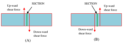
Positive Shear Force
Shear force which has a tendency to rotate an element of beam in clockwise direction i.e. if force act up-ward on the left and down-ward on the right of the element is considered as positive shear force.
A positive shear force is shown in figure ( A )
Negative Shear Force
Shear force which has a tendency to rotate an element of a beam in anti clockwise direction i.e. if force act down-ward on the left and up-ward on the right of the element is considered as negative shear force.
A negative shear force is shown in figure ( B )
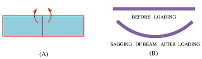
Positive Bending Moments or Sagging Moment
Bending moment which has a tendency to bend an element of beam in ∪ shape i.e. moment in clockwise on the left and anti clockwise on the right of element is considered as positive bending moments. A positive bending moment is shown in figure ( A ).
In this case, top fiber layers of the element are in compression and the bottom layers are in tension. The bending effect of this moment is shown in figure ( B ). Hence, a positive bending moment is often called as Sagging moment.
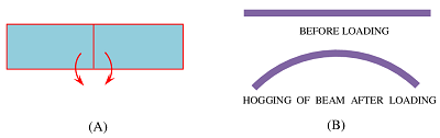
Negative Bending Moments or Hogging Moment
Bending moment which has a tendency to bend an element of beam in ∩ shape i.e. moment in anti clockwise on the left and clockwise on the right of element is considered as negative bending moment. A negative bending moment is shown in figure ( A ).
In this case, top fiber layers of element are in tension and the bottom layers are in compression. The bending effect of the moment is shown in figure ( B ). Hence, a negative bending moment is often called as Hogging moment.
See numerical problems based on this article.