What is called Lorentz Force?
When a charged body moves in a region of electric and magnetic field, it experiences a force of attraction or repulsion. This force is called Lorentz force. This Lorentz force is a combination of two forces –
- Electric Force – Force on the moving charge due to the electric field.
- Magnetic Force – Force on the moving charge due to the magnetic field.
Therefore, \text {Lorentz Force} = \text {Force on moving charge due to electric field} + \text {Force on moving charge due to magnetic field}
Or, \quad \text {Lorentz Force} = \text {Electric force} + \text {Magnetic force}
Or, \quad \vec {F} = \vec {F_e} + \vec {F_m} ………. (2)
Therefore, Lorentz force is the net force experienced by a moving charge in a region where an electric field and magnetic field both exist.
1.Electric Force
Consider that a charge ( q ) is moving in a region in which an electric field ( \vec E ) is present.
Then, from definition of electric field intensity –
Force experienced by a charge ( q ) in an electric field ( \vec {E} ) is given by –
\vec {F_e} = q \vec {E}
Direction of this electric force is in the direction of electric field ( \vec {E} ) .
2.Magnetic Force
Consider that a charge ( q ) is moving in a region in which a magnetic field ( \vec B ) is present.
Then, from definition of magnetic force due to magnetic effect –
Force on a moving charge ( q ) moving with velocity ( v ) at an angle ( \theta ) with direction of magnetic field ( \vec {B} ) , will be –
\vec {F_m} = q ( \vec {v} \ \times \ \vec {B} ) …….. (1)
Direction of this magnetic force is as per vector product rule of ( \vec {v} ) and ( \vec {B} ) .
Therefore, Lorentz force on the charge will be –
\vec {F} = q \vec {E} + q ( \vec {v} \ \times \ \vec {B} )
= q [ \vec {E} + ( \vec {v} \times \vec {B} ) ] ……… (3)
Lorentz Force on a conductor
A conductor contains a large number of free electrons which are the carriers of charge. These free electrons move in the conductor with drift velocity ( \vec {v} ) . The free electrons move in direction opposite to the direction of conventional current flowing in the conductor.
Therefore, if a current carrying conductor is placed in a magnetic field, free electrons will experience magnetic force which is transmitted to the conductor.
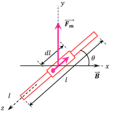
Consider about a conductor of length ( l ) carrying a current ( I ) . The conductor is placed in an uniform magnetic field ( \vec {B} ) as shown in figure. Let –
- Number of free electrons per unit volume of conductor is ( n ) .
- Area of cross-section of conductor is ( A )
- Charge on one electron is ( - e )
Therefore, magnetic force experienced by one electron will be –
\vec {f_m} = ( - e ) ( \vec {v} \ \times \ \vec {B} )
Force on an element of conductor
Consider a small element of length ( dl ) of conductor as shown in figure.
Then, number of free electrons in the element will be –
V = n \ \times \ A \ \times \ dl = ( nAdl )
Therefore, magnetic force experienced by element will be –
d \vec {F_m} = \text {Force on one electron} \ \times \ \text {Number of electrons}
= ( n A dl ) \vec {f_m}
= n A dl [ - e ( \vec {v} \ \times \ \vec {B} ) ]
So, \quad d \vec {F_m} = - n A e dl ( \vec {v} \ \times \ \vec {B} )
Drift velocity of electron is given by –
\vec {v} = \left ( - \frac {\vec {d l}}{dt} \right ) ( Minus sign is used because ( dl ) is in a direction opposite to the direction of ( \vec {v} ) )
So, \quad d \vec {F_m} = - n A e dl \left [ \left ( - \frac {\vec {d l}}{dt} \right ) \ \times \ \vec {B} \right ]
= n A e dl \left ( \frac {\vec {d l}}{dt} \ \times \ \vec {B} \right )
But, \quad ( n A dl ) e = dq ( Total charge in the element. )
Therefore, \quad d \vec {F_m} = dq \left ( \frac {\vec {d l}}{dt} \ \times \ \vec {B} \right )
= \left ( \frac {dq}{dt} \right ) ( \vec {d l} \ \times \ \vec {B} ) \quad \text {But,} \ \left ( \frac {dq}{dt} \right ) = I
= I \ ( \vec {d l} \ \times \ \vec {B} ) ………… (4)
Net Lorentz Force on conductor
Hence, net Lorentz force on conductor is obtained by integration –
\vec {F_m} = \int d \vec {F_m}
= \int I \ ( \vec {d l} \ \times \ \vec {B} )
= I \ ( \int \vec {d l} \ \times \ \vec {B} )
= I \ ( \vec {l} \times \ \vec {B} \ ) ………. (5)
This expression is the vector form to get the magnitude of net force on a conductor.
Analytical form of Net Lorentz Force
Consider that, the axis of a straight conductor is making an angle ( \theta ) in positive direction with the direction of magnetic field ( \vec {B} ) as shown in figure.
Then, magnitude of magnetic force will be –
\vec {F_m} = B I l \sin \theta ……….. (6)
Now, consider following situations –
(1) When ( \theta = 0 \degree ) \ \text {or} \ ( \theta = 180 \degree ) .
Then, ( \sin \theta = 0 ) .
Therefore, ( F_m = 0 ) . Hence, the conductor will experience no force.
(2) When ( \theta = 90 \degree ) .
Then, ( \sin \theta = 1 ) .
Therefore, ( F_m = BIl ) . Hence, the conductor will experience maximum force.
(3) If the conductor is not straight but curved, then it may be treated as a combination of many small straight conductors each of length ( dl ) .
Then, magnetic force [ F_m = \sum {I} ( d \vec {l} \ \times \ \vec {B} ) ]
(4) The magnetic force acting on any closed current loop or polygon in a uniform magnetic field becomes zero. In this case, lengths of elements form a closed polygon.
Hence, [ \oint {d \vec {l}} = 0 ]
Force between two parallel conductors
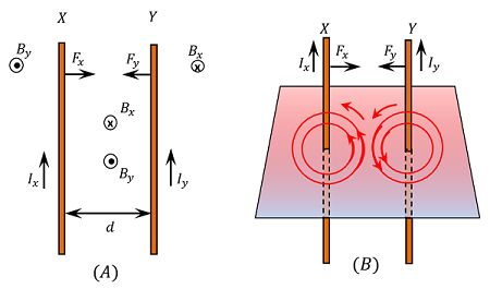
Consider about two infinitely long parallel conductors X and Y laying on a horizontal plane, as shown in figure. Let –
- Current in conductor X is ( I_x ) and
- Current in conductor Y is ( I_y ) .
- Directions of ( I_x ) \ \text {and} \ ( I_y ) are same.
- Distance between the conductors is ( d ) .
Force on Conductor Y due to Magnetic Field of Conductor X
Current in the conductor X will produce a magnetic field around itself as shown in figure. The intensity of this magnetic field at any point on the conductor Y will be –
B_x = \left ( \frac {\mu_0}{4 \pi} \right ) \left ( \frac {2 I_x}{d} \right ) …….. (1)
Direction of this magnetic field is obtained by right hand thumb rule. It is perpendicular to the plane of the conductor X and is directed vertically downwards ( i.e. penetrating into the plane of paper ) in the space between conductors X \ \text {and} \ Y .
We know that Lorentz force on a conductor carrying a current is –
F = B I l \sin \theta
Conductor Y is perpendicular to the magnetic field. Hence, ( \theta = 90 \degree )
Thus, \quad F = B I l
Therefore, force acting on unit length of the conductor Y will be –
F_y = B_x \times I_y \times 1 = B_x \ I_y
Putting the value of ( B_x ) from equation (1), we get –
F_y = \left ( \frac {\mu_0}{4 \pi} \right ) \left ( \frac {2 \ I_x}{d} \right ) I_y
Or, \quad F_y = \left ( \frac {\mu_0}{4 \pi} \right ) \left ( \frac {2 \ I_x \ I_y}{d} \right ) ……….. (2)
Now, by Fleming’s left hand rule, the direction of the force ( F_y ) is found directed towards conductor X .
Force on Conductor X due to Magnetic Field of Conductor Y
In similar manner, the force experienced per unit length of conductor X in the magnetic field ( B_y ) due to conductor Y is obtained as –
F_x = \left ( \frac {\mu_0}{4 \pi} \right ) \left ( \frac {2 \ I_x \ I_y}{d} \right ) ……….. (3)
By Fleming’s left hand rule, the direction of the force ( F_x ) is found directed towards conductor Y .
We find that, the forces ( F_x ) \ \text {and} \ ( F_y ) are equal but opposite in direction. So, these forces will pull the two conductors towards each other.
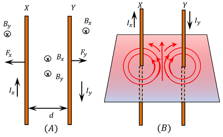
Hence, it is concluded that two long parallel conductors carrying currents in the same direction attract to each other. Similarly, two long parallel conductors carrying current in the opposite direction repel to each other.
Magnetic Field at the Middle
The space between two parallel conductors is under the influence of two magnetic fields ( B_x ) and ( B_y ) . If two conductors carry currents flowing in same direction, then direction of two magnetic fields in the space between the conductors will be opposite.
Magnitude of magnetic field at a distance \left ( \frac {d}{2} \right ) from the conductors will be equal but opposite in directions. Hence, the net magnetic field at middle of distance between two conductors becomes zero.
If currents in both conductors are flowing in opposite directions then the direction of two magnetic fields in the space between the conductors will be the same. Then the magnetic field at a distance \left ( \frac {d}{2} \right ) from the conductors will be equal and in the same direction. Hence, the net magnetic field at that point will be –
B = ( B_x + B_y )
= \left [ \left ( \frac {\mu_0}{4 \pi} \right ) \left ( \frac {2 I}{d / 2} \right ) + \left ( \frac {\mu_0}{4 \pi} \right ) \left ( \frac {2 I}{d / 2} \right ) \right ]
= 4 \times \left ( \frac {\mu_0}{4 \pi} \right ) \left ( \frac {2 I}{d} \right )
See numerical problems based on this article.