What is called a “Torque”?
Torque is the effect of a force that can cause an object to rotate about an axis. A force produces linear acceleration in an object which is in linear motion. In similar manner, a torque produces an angular acceleration in an object which is in circular or rotational motion.
Therefore, the turning effect produced by a force is called, moment of a force or torque.
A torque depends on two factors –
- The magnitude of the force ( F ) .
- The perpendicular distance ( d ) of the line of action of the force from the axis of rotation. It is called lever arm or moment arm.
Torque is measured by the product of force acting on the body and perpendicular distance of its line of action from the axis of rotation.
Therefore, torque is associated with Rotary motion of a body.
Rotary Motion
If a body has a motion in such a way that all its constituting particles move along circular paths in parallel planes, then the motion of the body is called a rotary motion.
The characteristics of a rotary motion are as follows –
- All the constituent particles of the body revolve in circular paths in same or different planes.
- The centers of these circular paths lie on a fixed line which is perpendicular to the parallel planes.
- This line is called the axis of rotation.
- If the angular velocity of the body is ( \omega ) , then all the constituting particles of the body will also rotate with same angular velocity ( \omega ) .
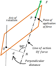
To understand a rotary motion, consider about a body as shown in figure.
The body is pinned at O so that it can rotate about a vertical axis through O .
A force ( F ) is applied on the body at point P . Let, ( d ) is the perpendicular distance of the line of action of force from the point O as shown in figure.
Then, torque acting on the body will be –
\tau = F \times d
Or, \quad \text {Torque} = \text {Force} \ \times \ \text {Moment arm}
Magnitude of Torque
Consider about a particle P on a body which rotate in the XY plane about an axis passing through origin O as shown in figure. Suppose –
- A force ( \vec F ) is acting on the particle.
- Force vector ( \vec F ) makes an angle ( \theta ) with the position vector ( \vec r ) of the particle.
- NP is the line of action of force vector ( \vec F ) .
A perpendicular ON is drawn from origin O . Then, from right angle triangle \triangle ONP , we get –
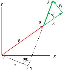
\left ( \frac {ON}{NP} \right ) = \sin \theta
Or, \quad \left ( \frac {d}{r} \right ) = \sin \theta
Therefore, \quad d = r \sin \theta
This is the perpendicular distance of line of action of force from the axis of rotation. Hence, moment arm or lever arm is ( r \sin \theta )
Therefore, torque acting on the body is –
\tau = \text {Force} \times \text {Moment Arm}
= F \times ( r \sin \theta ) = F d
Now, the force can be resolved into two rectangular components –
- Radial component ( F_r = F \cos \theta ) – It acts along the position vector ( \vec r ) . It doesn’t contribute to the torque.
- Angular or tangential component ( F_{\theta} = F \sin \theta ) – It acts perpendicular to the position vector ( \vec r ) . Only this component contributes for torque.
Therefore, \quad \tau = F \sin \theta . r = F_{\theta} . r
Therefore, \quad \tau = \text {Angular component of force} \times \text {Distance of angular component from axis of rotation}
Direction of Torque
Torque is the product of two vector quantities –
- Position vector ( \vec r )
- Force vector ( \vec F ) .
Hence, torque is a vector quantity. Its direction is always perpendicular to the plane containing the position vector ( \vec r ) and force vector ( \vec F ) .
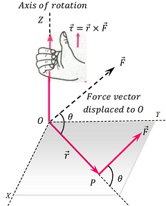
Right Hand Thumb Rule
Sense or direction of torque is determined by right hand thumb rule as shown in figure.
It states that –
If we curl the fingers of our right hand in the direction in which position vector ( \vec r ) is rotated to move into the position of force vector ( \vec F ) through the smaller angle between them, then the extended thumb gives the sense of torque.
Sign of torque
- A torque producing anti-clockwise turning effect is considered as positive torque.
- A torque producing clockwise turning effect is considered as negative torque.
Work done by a Torque
Consider about a body as shown in figure. Suppose, due to a tangential force ( F ) , the body makes an angular displacement of ( d \theta ) .
Then, work done by the torque in rotation of body will be –
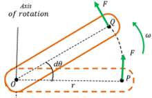
\Delta W = F \times \Delta S
Here, ( \Delta S ) is the distance moved by the force. It is equal to arc PQ .
Therefore, \quad \Delta S = \Delta \theta \times r
Or, \quad d W = F \times r \times d \theta = \tau d \theta
Therefore, \quad \text {Work done} = \text {Torque} \times \text {Angular displacement}
Total work done is obtained by integration method when torque is not uniform.
Therefore, \quad W = \int\limits_{\theta_1}^{\theta_2} \tau d \theta
Power of a Torque
Power is defined as the rate of work done.
Expression for work done by a torque is –
\Delta W = \tau \Delta \theta
Dividing both sides by \Delta t , we will get –
\left ( \frac {\Delta W}{\Delta t} \right ) = \tau \left ( \frac {\Delta \theta}{\Delta t} \right )
In this expression –
Term \left ( \frac {\Delta W}{\Delta t} \right ) represents power and, \left ( \frac {\Delta \theta}{\Delta t} \right ) represents angular velocity.
Therefore, Power of torque \quad P = \tau \omega
Or, \quad \text {Power of torque} = \text {Torque} \times \text {Angular velocity}
Torque & Moment of Inertia
Torque required to produce an angular displacement on a body depends upon the moment of inertia of that body.
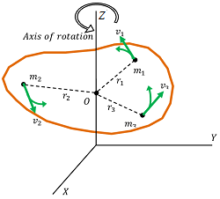
Consider about a body as shown in figure. For a rotating body, we know that –
- Angular velocity of each particle of rotating body is same.
- Therefore, angular acceleration for all particles of the body will also be the same.
- But linear acceleration of the particles will not be same. It will depend on their distances from the axis of rotation.
Now, consider about a particle P of mass ( m_1 ) at a distance ( r_1 ) from the axis of rotation.
Linear acceleration of the particle will be –
a_1 = r_1 \alpha
Hence, force acting on the particle will be –
F_1 = m_1 a_1 = m_1 r_1 \alpha
Moment of this force about the axis of rotation will be –
\tau _1=F_1 r_1= m_1 r_1^2 \alpha
Therefore, total torque will be –
\tau= \tau_1 + \tau_2 + \ ..... = m_1 r_1^2 \alpha + m_2 r_2^2 \alpha + \ .... etc.
But, ( \Sigma m r^2 ) represents moment of inertia of body about ( O ) . Hence, \quad \tau = I \alpha
Therefore, \quad \text {Torque} = \text {Moment of inertia} \times \text {Angular acceleration}
Rotational Kinetic Energy
Consider about a rigid body rotating about an axis OZ with uniform angular velocity ( \omega ) as shown in above figure above.
The body is considered to be made of ( n ) number of particles of masses ( m_1, \ m_2, \ m_3, \ .... \ m_n ) etc. situated at distances ( r_1, \ r_2, \ r_3, \ .... \ r_n ) etc. respectively from the axis of rotation.
The angular velocity of all particles will be same but their linear velocities will depend upon their distances from axis of rotation. So their linear velocities will be –
v_1 = r_1 \omega, \ v_2 = r_2 \omega, \ v_3 = r_3 \omega \ ........ etc.
Hence, total kinetic energy of rotation of body about OZ axis will be –
KE = \left ( \frac{1}{2} \right ) m_1 v_1^2 + \left ( \frac{1}{2} \right ) m_2 v_2^2 + \ ..... etc.
Or, \quad KE = \left ( \frac{1}{2} \right ) m_1 r_1^2 \omega^2 + \left ( \frac{1}{2} \right ) m_2 r_2^2 \omega^2 + ..... etc.
= \left ( \frac{1}{2} \right ) \left ( \Sigma mr^2 \right ) \omega^2
Therefore, \quad KE = \left ( \frac {1}{2} \right ) I \omega^2
\text {Kinetic Energy} = \left ( \frac {1}{2} \right ) \text {Moment of inertia} \times ( \text {Angular acceleration} )^2
See numerical problems based on this article.
