What is called a Lever?
A lever is a simple machine which is a rigid bar or a cylindrical rod capable to rotate about a fixed point called fulcrum point. Class of lever are based on the position of fulcrum point, load point and effort point.
- A lever is used as a force multiplier.
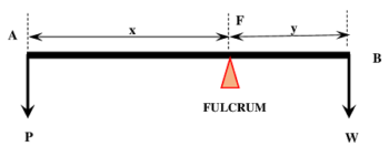
A straight lever is shown in figure below. The classification of lever and their performance are based upon certain special properties.
These special properties are called machine parameters. These are –
Load Point – The point of a lever at which external load or work is get as output is called load point. In figure point B is the load point.
Effort Point – The point at which input force or effort is applied to a lever is called effort point. In figure, point A is the effort point.
Fulcrum Point – The point about which a lever is capable to turn is called fulcrum point. In figure, point F is the fulcrum.
Load Arm – The length ( BF ) of the lever i.e. the distance between fulcrum point and load point is called load arm of lever. In figure ( y ) is the length of load arm.
Effort Arm – Length ( AF ) of the lever i.e. the distance between effort point and fulcrum point is called effort arm of lever. In figure ( x ) is the length of effort arm.
Classification of Levers
Levers are classified according to the relative positions of three important points i.e., load point, effort point and fulcrum point. According to their positions, levers are classified in three classes as follows –
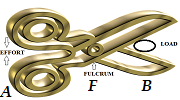
Class – 1 Lever
In class 1 lever, the fulcrum point F is located at the middle. Load point B is at one end of lever and effort point A is at the other end of lever as shown in figure.
EXAMPLE
- Scissors.
- Tongs.
- Claw hammer.
- Common balance.
- Pliers.
- Wrenches.
- See-saw.
- Straight lever etc.
Class – 2 Lever
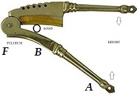
In class 2 lever, the load point B is located in the middle of lever. Fulcrum point F is at one end and effort point A is at other end of the lever as shown in figure.
EXAMPLE
- Betel nut cracker.
- Wheel barrow.
- Trolley bag.
- Bottle cap opener.
- Door panel etc.
Class – 3 Lever
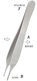
In class 3 lever, effort point A is located in between fulcrum point F and load point B as shown in figure.
EXAMPLE
- Human hand.
- Forceps.
- Stapler.
- Hockey stick.
- Fishing rod.
- Sweeping broom, etc.
Importance of Fulcrum of Lever
We use a simple machine to get an increased amount of output work by small input effort. Getting a higher mechanical advantage is our prime requirement.
Consider about a lever as shown in figure below. It is used to lift a heavy load (stone) from its position.
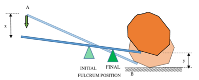
Here, value of load i.e. weight of stone is a fixed quantity. So, for effort to be less, effort arm should be large. This is only possible, if length of load arm is decreased.
Hence, to decrease the length of load arm, we have to shift the fulcrum point F towards load point B .
Therefore, velocity ratio of a lever depends upon position of fulcrum point. To get higher velocity ratio, we have to increase the ratio of effort arm to load arm of a lever. This ratio is known as Leverage Ratio.
\text {Leverage ratio} = \left ( \frac {\text {Length of effort arm}}{\text {Length of load arm}} \right )
As leverage ratio increases, velocity ratio and mechanical advantage both increases. But due to friction, the rate of increase of mechanical advantage is less than the rate of increase of velocity ratio.
In ideal conditions, friction is negligible. Therefore, ( VR = MA ) .
Therefore, by changing the position of fulcrum point, change in velocity ratio and mechanical advantage is get. Also friction has no affect on velocity ratio but mechanical advantage decreases due to increase in friction.
Compounding of Levers
To get higher mechanical advantage, two or more levers are connected together by hinged joints. This is called compounding of levers.
Why Levers are compounded?
Consider about a straight lever as discussed above. In this lever,
\text {Input work} = ( P \ \times \ x ) and
\text {Output work} = ( W \ \times \ Y )
Therefore, when friction is negligible \quad ( P \ \times \ x ) = ( W \ \times \ Y )
Or, \quad \left ( \frac {W}{P} \right ) = \left ( \frac {x}{y} \right )
So, \quad MA = \left ( \frac {W}{P} \right ) \text {or} \left ( \frac {x}{y} \right )
Therefore, it should be noted that to get higher mechanical advantage, we have to fulfill either of the following conditions –
- Load ( W ) should be much more in comparison to effort ( P ) i.e. ( W >> P )
- Effort ( P ) should be much less in comparison to load ( W ) i.e. ( P << W )
- Length of effort arm ( x ) of lever should be as large as possible.
- Length of load arm ( y ) of lever should be as small as possible.
But, due to certain constraints and space problem –
- Use of a very long lever is not possible.
- As per our will, we cannot decrease the load ( W ) , because it is a fixed quantity for a given task or work.
- As per our will, we cannot increase the effort ( P ) , because it is applied force by man power, which is limited.
Therefore, for increasing the mechanical advantage, the only possible option left is to adjust the position of fulcrum so that ( x >> y ) .
Hence, position of fulcrum point F should be so adjusted such that ( AF ) is much greater than the length ( BF ) .
But in case of using a straight lever for a huge work load the total length of lever (AF + BF) is also a limited quantity due to space constraint.
Hence, to get higher mechanical advantages, we use a combination of many levers in series.
This process of combining of many levers is called Compounding of levers.
Mechanical Advantage of a Compound Lever
A compound lever is used to get increased mechanical advantage or leverage ratio.
Consider about a simple compound lever as shown in figure. It is consisting of three straight levers or rods.
- Point A is the effort point and point D is the load point of lever.
- Points F_1 \ \text {and} \ F_2 are fulcrums points.
- Points B \ \text {and} \ C are movable hinges.
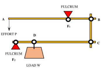
Let, an effort ( P ) is applied downward at point A . Thus, rod AB will exert an upward force on rod BC at hinge point B .
Let, ( R ) is the reaction exerted by rod BC at point B .
Then, by principle of moment of forces we get –
R \times BF_1 = P \times AF_1
Or, \quad R = P \left ( \frac { AF_1 }{ BF_1 } \right )
Now, rod BC will exert an upward pull ( R ) on lever C F_2 at point C .
Therefore, \quad R \times C F_2 = W \times D F_2
Or, \quad R = W \left ( \frac {DF_2}{CF_2} \right )
So, \quad \left ( \frac {W}{P} \right ) = \left ( \frac { AF_1 / BF_1 }{ DF_2 / CF_2 } \right )
Therefore, mechanical advantage of a compound lever will be –
MA = \left ( \frac{ AF_1 / BF_1 }{ DF_2 / CF_2 } \right )
= \left [ \left ( \frac {AF_1}{BF_1} \right ) \times \left ( \frac {CF_2}{DF_2} \right ) \right ]
Therefore, \quad \text {MA of compound lever} = \text {MA of lever} ( AB ) \ \times \ \text {MA of lever} ( CF_2 )