What is called an LCR circuit?
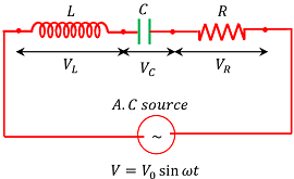
A circuit containing an inductor of pure inductance ( L ) , a capacitor of pure capacitance ( C ) and a resistor of pure resistance ( R ) joined in series across an AC supply is called a LCR circuit.
Phasor diagram of LCR circuit
Consider about an LCR circuit as shown in figure.
Let, ( V ) is the RMS value of the applied alternating emf and ( I ) is the RMS value of current to the circuit.
Now total effective opposition offered by the circuit is obtained with the help of phasor diagram as shown in figure.
The potential difference across the inductor –
V_L = I X_L ……… (1)
This potential difference or voltage leads the current ( I ) by an angle \left ( \frac {\pi}{2} \right ) . It is represented by OB perpendicular to the direction of ( I ) .
The potential difference across the capacitor –
V_C = I X_C ……… (2)
This potential difference or voltage lags behind the current ( I ) by an angle \left ( \frac {\pi}{2} \right ) . It is represented by OF perpendicular to the direction of ( I ) .
The potential difference across resistor –
V_R = I R ……… (3)
This potential difference or voltage is in same phase with the current ( I ) . It is represented by OA in the direction of ( I ) .
Since ( V_L ) and ( V_C ) are in opposite phases, so their resultant obtained by vector sum, \left ( V_L - V_C \right ) is represented by OD . Here, we have assumed that \quad \left ( V_L \ > \ V_C \right ) .
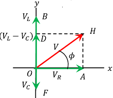
The resultant of ( V_R ) and \left ( V_L - V_C \right ) is represented by OH .
The magnitude of OH is given by –
OH = \sqrt {\left ( OH \right )^2 + \left ( OD \right )^2}
Or, \quad OH = \sqrt { V_R^2 + \left (V_L - V_C \right )^2 } .
Therefore, \quad V = \sqrt { V_R^2 + \left (V_L - V_C \right )^2 } ……… (4)
Impedance
Effective opposition offered by an LCR circuit is called impedance of the circuit.
Impedance is similar to the effective resistance of a circuit.
For an LCR circuit in which elements are connected in series to an AC supply, we have –
V = \sqrt { V_R^2 + \left (V_L - V_C \right )^2 }
We have the relations –
- For Inductance ( V_L = I X_L ) ……… (1)
- For Capacitance ( V_C = I X_C ) ……… (2)
- For Resistance ( V_R = I R ) ……… (3)
Therefore, from equations (1), (2) and (3) we get –
V = \sqrt { I^2 R^2 + \left (I X_L - I X_C \right )^2 }
= I \sqrt { R^2 + \left (X_L - X_C \right )^2 } .
So, \quad \left ( \frac {V}{I} \right ) = \sqrt { R^2 + \left (X_L - X_C \right )^2 } .
But \quad \left ( \frac {V}{I} \right ) = Z .
Where ( Z ) is the effective opposition offered by the LCR circuit. It is called impedance of the circuit.
Therefore, Impedance for an LCR circuit is given by –
Z = \sqrt { R^2 + \left (X_L - X_C \right )^2 } …….. (4)
Also, \quad \left ( \frac {V}{I} \right ) = Z
Therefore, \quad I = \left ( \frac {V}{Z} \right )
= \left ( \frac {V}{\sqrt { R^2 + \left (X_L - X_C \right )^2 }} \right )
= \left [ \frac {V}{\sqrt { R^2 + \left (L \omega - \frac {1}{C \omega} \right )^2 }} \right ] …….. (5)
Let ( \phi ) is the angle between ( V ) and ( I ) . Then from geometry of the figure –
\tan \phi = \left ( \frac {AH}{OA} \right ) = \left ( \frac {V_L - V_C}{V_R} \right )
= \left ( \frac {I X_L - I X_C}{I R} \right ) = \left ( \frac {X_L - X_C}{R} \right )
= \left [ \frac {\left ( L \omega - \frac {1}{C \omega } \right )}{R} \right ] ……. (6)
Power Factor of an LCR circuit
Ratio of true power and apparent power in an A.C circuit is called as power factor of the circuit.
\text {Power Factor} = \left ( \frac {\text {True Power}}{\text {Apparent Power}} \right )
Therefore, \quad PF = \left ( \frac {I V_R}{I V} \right )
= \left ( \frac {I^2 R}{I^2 Z} \right )
= \left ( \frac {R}{Z} \right )
In general, power factor of a circuit is represented by the cosine of angle ( \phi ) which is the phase difference between the voltage and the current.
From geometry of phasor diagram, we have –
\cos \phi = \left ( \frac {OA}{OH} \right )
= \left ( \frac {V_R}{V} \right )
= \left ( \frac {I R}{I Z} \right ) = \left ( \frac {R}{Z} \right )
Therefore, Power factor is given by –
\cos \phi = \left ( \frac {R}{Z} \right )
= \left [ \frac {R}{\sqrt {R^2 + \left ( X_L - X_C \right )^2}} \right ]
= \left [ \frac {R}{\sqrt {R^2 + \left ( L \omega - \frac {1}{C \omega} \right )^2}} \right ]
TO BE NOTED –
Power factor of a circuit is always positive and lies between 0 and 1 .
- For a pure resistive circuit, power factor ( \cos \phi = 1 )
- For a pure inductive circuit, power factor ( \cos \phi = 0 )
- For a pure capacitive circuit, power factor ( \cos \phi = 0 )
- For other type of circuits ( 1 \ > \ \cos \phi \ > \ 0 )