What is Dielectric Constant?
Dielectric constant of a medium is defined as the ratio of electrostatic force ( F_{air} ) between two point charges separated by a certain distance in air to the electrostatic force ( F_{medium} ) between the same two point charges kept at same distance in the medium.
Therefore, \quad \text {Dielectric Constant of medium} = \left ( \frac {\text {Electrostatic force in air}}{\text {Electrostatic force in medium}} \right )
Coulombs law for electrostatic force is modified and written as –
F_{medium} = \left ( \frac {1}{K} \right ) \left ( \frac {q_1 q_2}{r^2} \right ) …… (1)
For air or vacuum, dielectric constant ( K_{air} = 1 ) . Hence, electrostatic force in air will be –
F_{air} = \left ( \frac {q_1 q_2}{r^2} \right ) …. (2)
Dividing equation (2) by equation (1), we will get –
K_{medium} = \left ( \frac {F_{air}}{F_{medium}} \right ) ……. (3)
Dielectric constant is a ratio of two similar quantities. Hence, it is dimension-less and has no unit.
Permittivity
Permittivity of a medium is defined as a measure of ability of the medium for electric polarization.
A medium with high permittivity polarizes more in response to an applied electric field in comparison to a material with low permittivity.
In the presence of electric field, the medium itself get polarized. The polarized medium opposes the interaction between two charged particles kept in that medium. Therefore, the effect of permittivity of a medium is to reduce the electrostatic force between the charged particles.
Therefore, if the permittivity of a medium is high –
- The medium will polarize more easily.
- It will permit flow of charges more easily.
- It will oppose more to the interaction between two point charges and decrease the force of interaction between them.
Absolute Permittivity
Permittivity of air or vacuum or free space is known as absolute permittivity of free space.
It is denoted by ( \epsilon_0 ) and its value is –
\epsilon_0 = 8.854 \times 10^{-12} \ C^2 \ N^{-1} \ m^{-2}
Relative Permittivity
Relative permittivity is defined as the ratio of permittivity of medium with respect to the permittivity of free space or vacuum or air.
Therefore, \quad \epsilon_r = \left ( \frac {\epsilon}{\epsilon_0} \right )
By Coulomb’s law, electrostatic force between two charges ( q_1 ) and ( q_2 ) kept at a distance ( r ) is given by –
F_{medium} = k \left ( \frac { q_1 q_2 }{ r^2 } \right )
Here, ( k ) is a Coulomb’s constant. Its value is given by –
k = \left ( \frac {1}{4 \pi \epsilon} \right ) = \left ( \frac {1}{4 \pi \epsilon_0 \epsilon_r} \right )
In above expression –
- ( \epsilon ) is called the permittivity of the medium.
- ( \epsilon_0 ) is called the absolute permittivity of free space.
- ( \epsilon_r ) is the relative permittivity of the medium with respect to air.
Therefore, magnitude of electrostatic force in given medium will be –
F_{medium} = \left ( \frac {1}{4 \pi \epsilon_0 \epsilon_r} \right ) \left ( \frac { q_1 q_2 }{ r^2 } \right ) ……… (4)
For free space or air ( \epsilon_r = 1 )
Therefore, magnitude of electrostatic force in air will be –
F_{air} = \left ( \frac {1}{4 \pi \epsilon_0} \right ) \left ( \frac {q_1 q_2}{r^2} \right ) ………. (5)
Dividing equation (5) by equation (4), we will get –
\epsilon_r = \left ( \frac {F_{air}}{F_{medium}} \right ) ….. (6)
Therefore, relative permittivity of a medium is defined as the ratio of the electrostatic force ( F_{air} ) between two point charges separated by a certain distance in air to the electrostatic force ( F_{medium} ) between the same two point charges kept at same distance in the medium.
Relative permittivity is a ratio of two similar quantities. Hence, it is dimension-less and has no unit.
Relation between Relative Permittivity & Dielectric Constant
From equation (3), dielectric constant of a medium is given as –
K_{medium} = \left ( \frac {F_{air}}{F_{medium}} \right ) ……. (3)
From equation (6), relative permittivity of a medium is given as –
\epsilon_r = \left ( \frac {F_{air}}{F_{medium}} \right ) ….. (6)
Therefore, \text {Relative permittivity of a medium} = \text {Dielectric constant of that medium}
Dielectric Substance
A dielectric substance is defined as a non conducting substance which has no free electrons or has very few free electrons such as air, glass, mica, paraffin wax etc.
The molecules of dielectric substances may be polar or a non-polar molecule.

Polar Dielectric
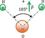
If the centre of mass of positive charge (i.e. protons) does not coincide with the centre of mass of negative charge (i.e. electrons) then the molecule is said to be a polar dielectric.
Polar molecules do not have symmetrical shapes. They have permanent dipole moment ( \vec {p} ) .
A water molecule is a polar molecule as shown in figure.
Examples –
HCl, \ H_2O, \ NH_3, \ CO_2, alcohol etc. are polar molecules.
Effect of Electric Field on Polar Dielectric

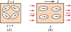
In the absence of any electric field, the molecules of polar substance are randomly oriented. These molecules remain aligned themselves in the form of closed chains as shown in figure (A).
When an electric field ( \vec {E} ) is applied across a polar dielectric molecule called a dipole, each molecule experiences a torque. This torque tends to align the molecules in the direction of the electric field as shown in figure (B).
After alignment in the direction of electric field, the dipole moment of all the molecules get added. This is the reason that the polar dielectric has finite net dipole moment in the presence of external electric field.
Non-polar Dielectric
If the centre of mass of positive charge (i.e. protons) coincides with the centre of mass of negative charge (i.e. electrons), then the molecule is said to be a polar dielectric molecule.

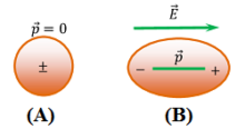
A non polar molecule has symmetrical shape. In the absence of any electric field the dipole moment of a non-polar molecule is zero.
A non-polar molecule is shown in figure (A). Figure (B) shows elongation of the molecule under the effect of electric field.
Examples –
N_2, \ O_2, \ H_2, \ CO_2, methane, benzene etc. are non-polar molecules.
Effect of Electric Field on non-polar Dielectric
When a non polar molecule is placed in an uniform electric field ( \vec {E} ) , positive charges of molecules experience a force of ( \vec {F} = q \vec {E} ) in the direction of electric field and negative charges experience a force of ( \vec {F} = - q \vec {E} ) in a direction opposite to the direction of electric field.
Thus, the centres of mass of positive and negative charges displaced in opposite directions and the molecules get elongated as shown in above figure (B).
Therefore, a non-polar molecule becomes a polar molecule under the influence of a strong electric field.
The dipole moment of such a molecule is called induced dipole moment. Induced electric dipole moment disappears as soon as the external electric field is removed.
Polarizability
Polarizability of a dielectric molecule states that –
For a molecule, the induced electric dipole moment ( \vec {p} ) is directly proportional to the applied electric field ( \vec {E} )
Therefore, \quad \vec {p} \propto \epsilon_0 \vec {E}
= \epsilon_0 \ \alpha \ \vec {E}
Here, \alpha is a proportionality constant called atomic or molecular polarizability. Therefore, molecular polarizability is given by –
\alpha = \left ( \frac {\vec {p}}{\epsilon_0 \vec {E}} \right )
The SI unit of atomic or molecular polarizability is ( m^3 ) .
Polarization of Dielectric
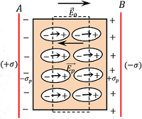
Consider about two parallel conducting plates separated by a distance and charged with equal but opposite sign charges.
Let, ( + \sigma ) \ \text {and} \ ( - \sigma ) are the surface charge density for positive and negative plates respectively. Then magnitude of electric field between the plates will be –

E_0 = \left ( \frac {\sigma}{\epsilon_0} \right ) ………. (1)
Now, if a slab of non polar dielectric substance is inserted between the plates, then each atom or molecule of dielectric will become elongated due to effect of electric field. These tiny dipole molecules will align themselves in the direction of electric field as shown in figure.
Therefore, the net effect of electric field in dielectric slab is that, the opposite faces of the dielectric slab will have equal and opposite charges.
These charges are called induced charges and this process is called polarization of the dielectric.
These Induced charges in dielectric will develop a field called induced electric field, ( \vec {E_p} ) . Let, ( \sigma_p ) \ \text {and} \ ( - \sigma_p ) are the induced surface charge densities set up in the opposite faces of dielectric slab.
Then, \quad \vec {E_p} = \left ( \frac {\sigma_p}{\epsilon_0} \right )
This acts in a direction opposite to the direction of applied electric field. Therefore, the net electric field inside the dielectric will be –
E = ( E_0 - E_p )
= \left [ \left ( \frac {\sigma}{\epsilon_0} \right ) - \left ( \frac {\sigma_p}{\epsilon_0} \right ) \right ]
= \left ( \frac {\sigma - \sigma_p}{\epsilon_0} \right )
Hence, electric field intensity reduced when a dielectric slab is placed between parallel plates.
The net electric field intensity [ E = ( E_0 - E_p ) ] is known as reduced value of electric field.
